Operation, Prism 3000, 0 introduction – Verilink PRISM 3000 (34-00184) Product Manual User Manual
Page 17: 1 front panel operation
Operation
3-1
PRISM 3000
Operation
3.0
Introduction
This chapter describes the screens and menus associated
with the TxPORT PRISM 3000 front panel LCD interface.
The ‘Terminal Operation’ chapter discusses the screens and
menus associated with the external terminal interface. In
general, the options are the same for both interfaces.
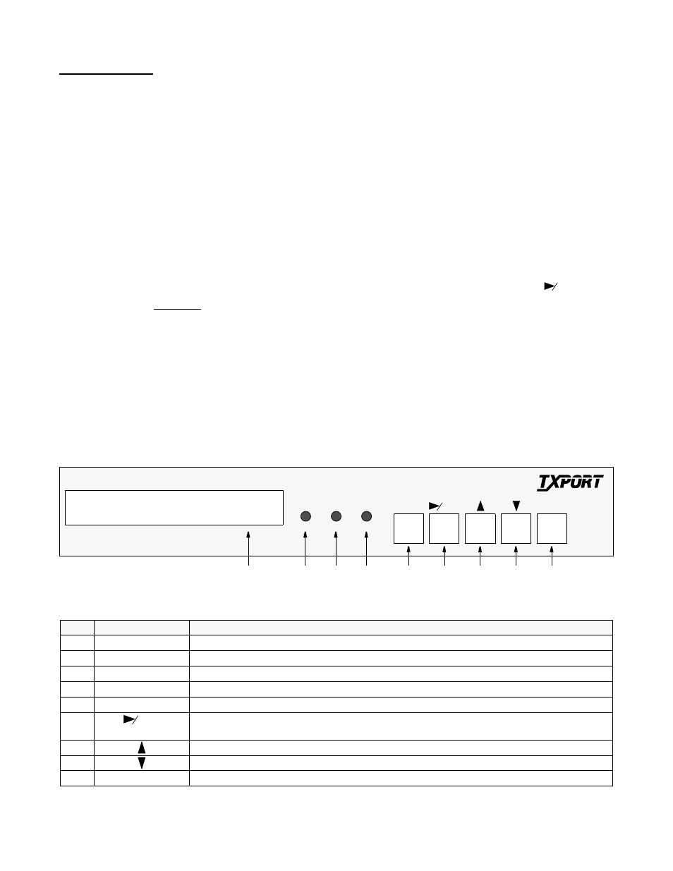
The
illustration on this page
depicts the front panel which
has three LED indicators, an LCD screen, and five control
buttons. The
table below the illustration
is referenced by
number to the front panel controls and indicators along with
a brief description.
NOTE: Throughout this manual, all the factory default
settings are shown underlined.
3.1
Front Panel Operation
After power is applied and the unit performs a self test, the
idle display screen appears as
shown in the illustration
below
. The top display line is text that may be user pro-
grammed (see ‘User Info’,
). The
bottom line displays the unit serial number and the
hardware/software revision numbers. The unit may be
accessed by pressing any front panel key.
3.1.1
Maintenance Reset
The PRISM 3000 provides non -volatile memory retention
of unit configuration in the event of power failure. This fea-
ture allows the unit to automatically restore normal service
following a power loss. Note, however, that when the unit is
stored without power for an extended period, the battery
may drain and some parameters may become corrupted.
Therefore, when the unit is first received for installation or if
power has not been applied for an extended period, a factory
default ‘maintenance reset’ operation should be performed.
This is done by pressing and holding the ‘
’ button
and then applying power to the unit. Hold this key until the
‘
RAM
CLEARED
’ message appears. This procedure installs
the predefined ROM configuration to eliminate the possibil-
ity of data corruption. The battery is fully charged after
power has been applied for 160 hours.
NOTE: The maintenance reset operation sets all
parameters to the factory default ROM settings and
zeros all performance registers.
CLR
Index
Control/Indicator
Function
1
LCD Display
This 2- line, 40- character wide window provides access to unit configuration, diagnostics, and utilities.
2
ALARM (red)
This LED lights continuously when the unit is in an active alarm condition.
3
TEST (yellow)
This LED lights continuously when line or DTE loops are set or if the BERT function is operating.
4
POWER (green)
This LED lights continuously when power is applied to the unit.
5
EXIT
Pressing this button returns the user to the previous menu.
6
CLR
Pressing this button will either move the cursor one character to the right or it will clear the error counts.
Pressing this button on power up resets all parameters to the factory defaults.
7
Pressing this button allows the user to scroll up through the elements/parameters.
8
Pressing this button allows the user to scroll down through the elements/parameters.
9
SELECT
Pressing this button accesses a submenu or sets a parameter to the displayed value.
ALARM TEST POWER
SELECT
CLR
EXIT
1
TxPORT PRISM 3000
S/N:xxx
HW Rev x.xx
SW Rev x.xx
PRISM 3000
2
3
4
5
6
7
8
9
T
R
A
N
S
P
O
R
T
®
Front Panel Controls and Indicators