Verilink PRISM 3000 (34-00184) Product Manual User Manual
Page 12
PRISM 3000
2-2
Installation
AC Version
l
O
NC C NO GND
110 /220 VAC
1.0A
.4A /.2A
NMS
IN
ALARM
RELAY
ETHERNET
PORT 2
PORT 1
PORT 3
PORT 4
NMS
OUT
SUPV
STA
CLK
T1
DTE
T1
NET
DC Version
1
2
3
OFF
ON
2 A
250 V
DCV RET GND
10
9
8
7
6
4
11 12
14
13
5
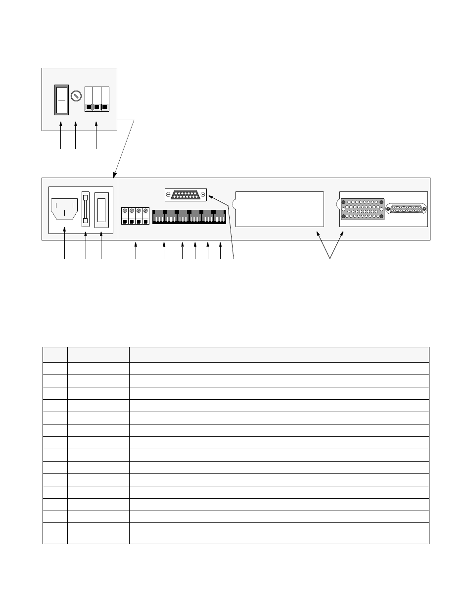
Figure 2-1
PRISM 3000 Rear Panel
Index
Control/Indicator
Function
1
DC Power Switch
This switch turns the DC power ON or OFF.
2
DC Fuse
This DC fuse is rated at 2.0 Amp.
3
DC Connection
48 VDC power is connected to ‘
DCV
’; the return is connected to ‘
RET
’. See
.
4
AC Connection
This 110/220 VAC power receptacle is rated at 50-60 Hz, 0.6 A / 0.3 A. See
.
5
AC Fuse
This AC fuse is rated at 1.0 Amp and is shipped with a spare.
6
AC Power Switch
This switch controls the AC power (position
I
is ON and position
O
is OFF).
7
Alarm Relay
The ‘Normally Closed’ alarm connects to NC & C. The ‘Normally Open’ alarm connects to NO & C.
8
NMS
This is the network management system input/output. Refer to
.
9
SUPV
Supervisory port connection. Refer to
.
10
Station Clock
The N x 56/64 kHz or 1.544 MHz external station clock connector. Refer to
.
11
T1 DTE
The T1 DTE port for drop and insert applications. Refer to
.
12
T1 NET
The T1 network port. Refer to
.
13
Slot 1 - Ethernet
This is the 15-pin Ethernet or Token Ring connection. Refer to
.
14
Ports 1 through 4
Two cards with up to two ports each may be inserted into each of these slots. Ports 1 and 2 show a combi-
nation of V.35 and EIA530 cards.