System led, M1-3 alarms, Alarm indications – Verilink M1-3 (880-503136-001) Product Manual User Manual
Page 51: Alarm information, System led -3, M1-3 alarms -3, Alarm indications -3 alarm information -3, Status code -3
Performance Monitoring
Verilink M1-3 User Manual
4-3
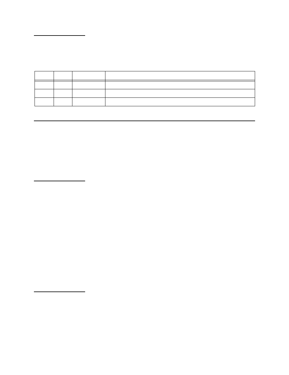
System LED
The System LED displays node communication conditions. For
example, the system LED can also turn red for a loss of clock
condition, activating a critical alarm.
provides a
description of the System LED states:
Table 4-3
System LED Indicator
M1-3 Alarms
The SCM polls the various modules for alarms. If alarm reporting is
enabled for the node and for the M1-3, the SCM retrieves and sends
the alarm to the Craft interface, Node Manager, or an SNMP agent.
Alarms can be automatically sent to a specified printer by setting
up the printer address in the SCM management utilities menus.
Alarm
Indications
The alarm list displays the following:
•
Whenever the system powers up and any module performs a
self-test
•
Power supply input is lost
•
A default or user-designated threshold is exceeded
•
A Yellow Alarm is received from the network (DS1)
•
An unframed all-ones or alarm indication signal (AIS) is
received from the network (DS1)
•
There is a loss of signal (LOS) or loss of frame (LOF) (DS1/DS3)
•
A loopback is present
•
A module fails
•
A module is removed from the shelf
Alarm
Information
The SCM alarm listing displays the following information about the
alarms.
shows an example of an M1-3 alarm report.
Status Code
The Status Code column displays a decimal code on an ASCII
terminal.
State
Color
Alarm Class
Error Condition
Solid
Green
None
M1-3 module is okay.
Solid
Red
Critical
System failure—Check the performance status or alarm status screens.
Off
None
None
M1-3 module has no power.