Maintenance screen -11, Clear tests -11 clear alarms -11, Test loops -11 – Verilink 2000 (34-00182) Product Manual User Manual
Page 45: Maintenance screen
Maintenance Screen
4-11
Maintenance
Screen
The Maintenance screen (Figure 4-7) allows performing test and maintenance
functions on the T1 circuit. BERT is performed using on -board test facilities.
Therefore, no other test equipment is needed. Actions initiated by each field are
detailed in the following paragraphs.
Clear Tests
Pressing Enter on this field clears all tests and any loops that have been initiated.
Clear Alarms
Pressing Enter on this field clears all near-end alarms.
Test
Loops
Loop status changes can be made only when the BERT function is not in the active
mode. The line may be taken out of service by inducing loops at each end. The
CSU recognizes in-band and FDL out-of-band loopback requests as well as local
or remote network manager loopback configurations. The unit supports a multitude
of ways to test the service to and from the CSU. The CSU has loopback and BERT
functions as described in the following paragraphs.
The CSU monitors network loopback commands and activates loops based upon
their reception as described in TR54016 and T1.403. Loops may be activated
through the terminal interface via the supervisory port or through the network
manager. A loop may also be activated by the front panel test switch. The normal
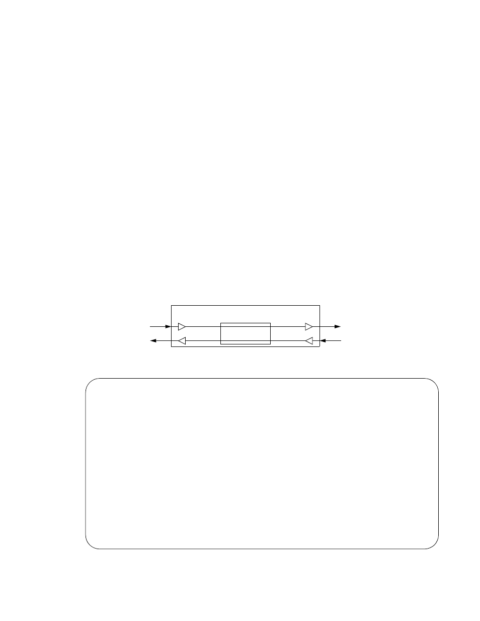
operating mode of the CSU in a non-loop condition is shown in Figure 4-8.
2000 CSU x.xx/x.xx
2000 CSU Date
MM/DD/YY
2000 CSU x.xx/x.xx
(Unit Address: xxx)
Time HH:MM:SS
----------------------------- ELEMENT MAINTENANCE
------------------------------
(CLEAR TESTS)
Pattern: [QRSS]
(CLEAR ALARMS
Test Length: [15 min]
T1 Loop: [NET LLB][AIS ]
Pattern Sync: IN SYNC
T1 Unloop: [DTE PLB]
Elapsed Time: 01:15:00
Far LLB: [Unframed]
Bit Errors: 5
Errored Seconds: 3
% EFS: 97.5
(START TEST)
NET Status: OK
(RESET ERRORS)
DTE Status: OK
Near Loops: -------/-------/-------/-------
Far Loops: -------/-------
Figure 4-7 Maintenance Screen
Framing, CRC, FDL
Tx
Rx
Rx
Tx
DTE
Interface
NET
Interface
Figure 4-8 Normal Operation