Alarm controls and indicators – Verilink 2000 (34-00182) Product Manual User Manual
Page 32
3-2
O
PERATION
Alarm Controls
and Indicators
3
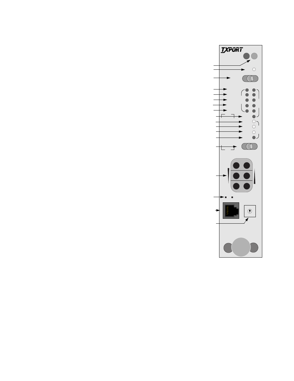
ACO: This yellow LED lights whenever the alarm
cut off switch is placed in the left ON position. It
indicates that the alarm relay contacts are disabled.
4
ACO SW: The alarm cut off switch controls the
alarm relay circuitry. If the switch is placed in the
left ON position, this circuitry is deactivated. The
right OFF position enables the contacts to report
alarm conditions.
5
BV /CR / FE: This LED lights one second for each
second with an occurrence of bipolar violations
(BPV), cyclic redundancy check (CRC) errors, or
frame bit errors (FBE).
6
LOS/OOF: This LED blinks with loss of signal
(LOS) from the network or DTE. It lights constantly
when an out of frame (OOF) condition is detected.
7
AIS: This alarm indication signal LED lights if an
unframed all ones condition is detected from the
network or DTE.
8
REM ALM: This LED lights constantly when a
remote (yellow) alarm signal is received.
9
LOC ALM: This LED lights when a local alarm
exceeding alarm thresholds exists.
10
DENSITY: This LED lights when a low ones
density is received from the equipment.
Test Controls
and Indicators
11
LLB: This LED lights continuously when the network interface is in line
loopback. It flashes when the DTE interface is in line loopback.
12
PLB: This LED lights continuously when the network interface is in payload
loopback.
STATUS
ACO SW
BV/CR/FE
LOS/OOF
AIS
REM ALM
LOC ALM
S
U
P
V
ACO
N
E
T
D
T
E
T
S
T
LOC
FAR
DENSITY
LLB
PLB
TST
ERR
TO
NET
FRM
NET
MON
MON
TO
DTE
FRM
DTE
PAT SEL
0
1
2
3
4
5 6
7
9
8
T
R
A
N
S
P
O
R
T
®
2000
ESF CSU
17
2
3
1
4
5
6
7
8
9
10
11
12
13
14
15
16
18
Figure 3-1 2000 CSU
Front Panel