Configuration switch s3 -4, Network lbo -4 dte lbo -4 – Verilink 2000 (34-00182) Product Manual User Manual
Page 16
2-4
I
NSTALLATION
Configuration
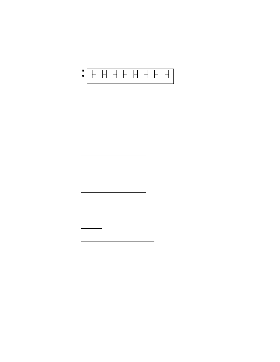
Switch S3
Switch S3 (Figure 2-2) is used to set the configuration parameters listed in the
following paragraphs. Refer to the Terminal Operation chapter of this manual for
more information on the related software-controlled configuration commands.
Network LBO
Positions S3 -1 and S3-2 set the line build out signal level of the transmit data
(TXD) from the unit to the network. The output level is factory set at 0 dB. It may
be attenuated by -7.5 dB, -15 dB, or -22.5 dB if operating conditions require that
it be changed. The telco should provide the proper setting to the user.
If unsure of
the exact setting, then leave it at the default value. The values are listed in
Table 2-1.
DTE LBO
Positions S3-3, S3-4, and S3-5 set the line build out to one of the values listed in
Table 2-2. The transmit output level is selectable according to the cable length
between the DTE port and the attached equipment. The factory default setting is
0-110 feet.
Table 2-1 Network LBO
S3-1
S3-2
Network LBO
Dn
Dn
0 dB
Dn
Up
-7.5 dB
Up
Dn
-15.0 dB
Up
Up
-22.5 dB
Table 2-2 DTE LBO
S3-3
S3-4
S3 -5
DTE LBO
Dn
Dn
Dn
0 -110 ft
Dn
Dn
Up
110-220 ft
Dn
Up
Dn
220-330 ft
Dn
Up
Up
330-440 ft
Up
Dn
Dn
440-550 ft
Up
Dn
Up
550-655 ft
Up
Up
Dn
> 655 ft
Up
Up
Up
Square
7
6
5
4
3
2
1
8
Dn
Up
NE
T
L
B
O
NE
T
L
B
O
DT
E
L
ev
el
DT
E
L
ev
el
DT
E
L
ev
el
C
loc
k
So
ur
ce
C
loc
k
So
ur
ce
C
loc
k
So
ur
ce
Figure 2-2 Switch S3