Chassis assembly -3, Unit configuration -3, Unit configuration – Verilink 2000 (34-00182) Product Manual User Manual
Page 15
Unit Configuration
2-3
Chassis
Assembly
Up to 12 units may be inserted into a chassis and the chassis may be installed in a
19-inch or 23-inch rack using four screws. Connections are made from the rear of
the chassis. Refer to Figure 2-9 and Figure 2-10 on page 2 -17 for these
illustrations.
Unit
Configuration
The 2000 CSU may be configured and controlled in a variety of modes. For use
without the intelligent Terminal Interface, the EM8000 Network Manager, or the
8100A Site Controller, the CSU can be configured from several switches accessible
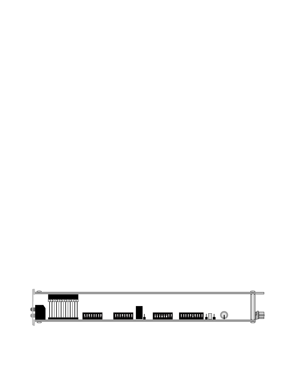
along the side of the circuit boards (see Figure 2-1).
For more functionality, the CSU can be software controlled from a terminal via the
RS-232 serial port connected to the unit. The Terminal Interface application
program is firmware embedded in each CSU and is discussed in the Terminal
Operation chapter of this manual. The EM8000 Network Manager and 8100A Site
Controller provide a similar set of capabilities (refer to the EM8000 or 8100A
reference manual).
The following pages briefly discuss the switch configuration options of the CSU.
This installation guide assumes that the user understands the meaning of each
setting and knows how the unit is to be configured.
Three 8-position DIP switches are located on the circuit board. The numbering
system used for each switch position is as follows: Position 2 of Switch S3 is
referred to as Switch S3-2, and so on. Each switch may be placed in either the up
or down position, with down being next to the switch position number printed on
the switch body.
In addition to the three configuration DIP switches, there is a 10-position DIP
switch used to set the CSU unit address for use with the EM8000 Network
Manager or 8100A Site Controller. Also, a slide switch is used to enable and
disable the sealing current and a jumper is used to select the alarm relay mode.
Before installation, verify each configuration switch setting. Two removable
configuration guides are included in the rear of this manual to record option
selections for future reference. Differences in the use of configuration switches
between the CSU stand -alone unit and the CSU chassis mount module are noted in
the appropriate places.
Figure 2-1 Circuit Board View
1 2 3 4 5 6 7 8
1 2 3 4 5 6 7 8
1 2 3 4 5 6 7 8
1 2 3 4 5 6 7 8 9 10
S3
S4
J1
S5
S6
LBO/Clock
Configuration
Configuration
Alarm
NMS Address