Csu timing source -5, Configuration switch s4 -5, T1.403 performance reporting -5 audible alarm -5 – Verilink 2000 (34-00182) Product Manual User Manual
Page 17
Unit Configuration
2-5
CSU Timing Source
In the normal mode of operation, CSUs clock out transmit data toward the network
using the timing derived by the data received from the DTE. Data transmitted
toward the DTE is clocked out using the timing derived by the data received from
the network.
For unique applications, the 2000 CSU allows timing to be derived from a single
source for data transmitted toward both the network and DTE. Positions S3 -6,
S3-7, and S3 -8 are used to set the CSU’s transmit timing source to one of the
values listed in Table 2-3.
For normal operation, S3-6, S3-7, and S3-8 should all be set to the Down position.
Configuration
Switch S4
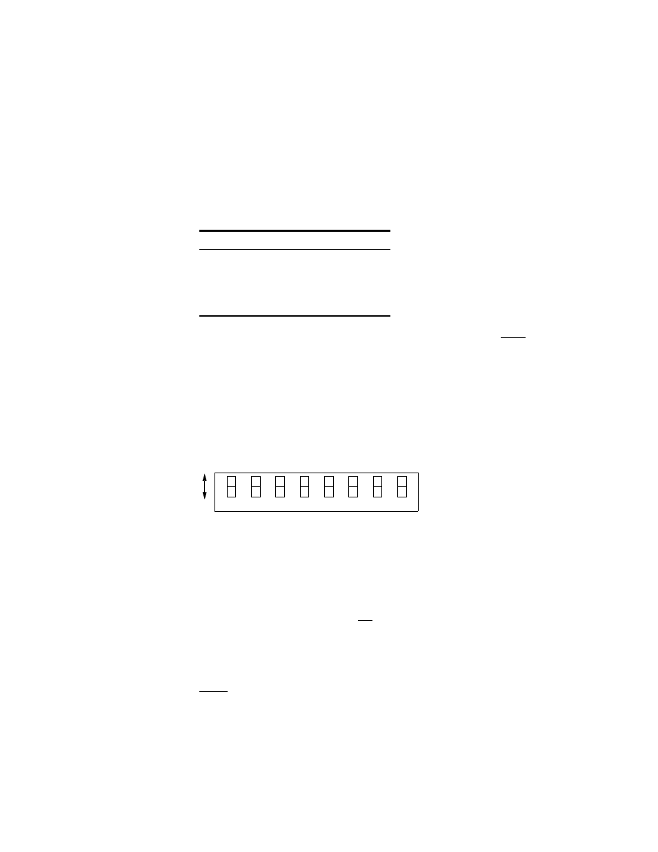
Switch S4 (see Figure 2-3) is used to set the configuration parameters listed in the
following paragraphs. Detailed information on the connection and use of the
Supervisory and NMS ports is found in Network Management on page 2-11.
T1.403 Performance Reporting
The 2000 CSU conforms to ANSI standard T1.403. However, it allows turning the
performance report message (PRM) On or Off with Switch S4- 1.
Down: PRM enabled
Up: PRM disabled
Audible Alarm
Position S4-2 enables the piezo buzzer, which indicates an alarm condition.
Down: Disabled Up: Enabled
Table 2-3 Timing Source
S3-6
S3-7
S3 -8
Timing Source
Dn
Dn
Dn
Normal
Up
Dn
Dn
Internal
Up
Up
Dn
Network
Up
Up
Up
DTE
Dn
Up
7
6
5
4
3
2
1
8
T1
.40
3
PRM
Au
di
bl
e
Al
ar
m
B
o
ot
Mo
de
B
o
ot
Mo
de
SU
PV
Rat
e
SU
PV
Rat
e
N
MS Ra
te
N
MS Ra
te
Figure 2-3 Switch S4