Warning – Triplett 9320-A User Manual
Page 30
29
Triplett Model 9320-A
then pressing the SELECT button until the
annunciator appears in the display.
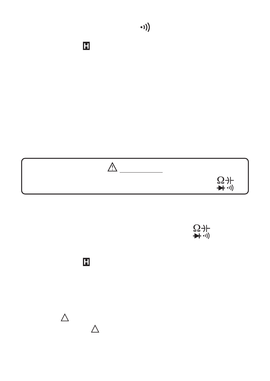
Make certain that the
annunciator on the display is not visible. If it is visible,
press the D-HOLD button to turn it off.
Attach the test leads to the Tester. The red lead is connected to the V
Ω
Hz Jack,
and the black lead is connected to the COM Jack. With the leads open, the display
should display the Overrange OL indication. Short the leads together. The Conti-
nuity beeper should sound and display should indicate about “000.0” Ohms.
Connect the test probes to the device or circuit to be tested. If the resistance is
less than 50 to 150 Ohms, the continuity beeper will sound.
The reading displayed on the LCD is an approximate indication, in Ohms, of the
resistance of the device or circuit being measured.
9.6 Capacitance Test
WARNING!!!
Do not apply voltage or current to the meter when it is set to
Refer to Section 7.0, Preparation For Use, and Section 8.0, General Measurement
Procedures, before attempting any measurements.
Select Diode Test by rotating the FUNCTION switch to the
position and
then pressing the SELECT button until the nF annunciator appears in the display.
Make certain that the
annunciator on the display is not visible. If it is visible,
press the D-HOLD button to turn it off.
Attach the test leads to the Tester. The red lead is connected to the V
Ω
Hz Jack,
and the black lead is connected to the COM Jack. With the leads open, the display
usually displays from “01.XX” to “03.XX” nF (where the X’s indicate that any number
can be displayed). This is the residual capacitance error. To “zero out” this error,
press the REL
and DCA ZERO ADJ button. The displayed reading should change
to 00.00nF, and the REL
annunciator should appear in the display.