Connecting to the vx640, Fiber optic cable – Thinklogical VX640 Router Manual User Manual
Page 21
VX640 Router Manual, Rev. F
16
November, 2013
Step 3
Verify that the four power supplies, located above the fan tray, are secure in the chassis.
Step 4
Verify that the fan tray is fully seated in the chassis and that the thumb screws are secure.
Note: If mounting the chassis in a rack, insure that air flow to the fans and the front door
is not restricted.
Step 5
The temperature in the chassis is monitored by internal temperature sensors in several locations.
Sensors located in the Power Supplies, Fan Trays, on the Controller Card(s), on the I/O Card(s),
and on the Switch Cards monitor continuously for any anomalous conditions.
Note: If any of these sensors detect an over temperature condition, power will be removed
from all sensitive components and the system will shut down.
Step 6
All fan speeds are monitored. Any fan speed that does not meet specification will cause an alarm
condition.
Warning!
Do not open or remove the front door for more than a few minutes when the unit
is powered. (The door includes air-flow baffles that are part of the cooling system.) The
Switch Card integrated circuits may overheat when operating without the front door
closed.
Note: All failure conditions send out notifications prior to shut down. For a detailed list of
the alarm functions, see page 10: Alarm Descriptions for the VX640.
Step 7
When the VX Router has been inspected and found to be in suitable condition, the installation
process can begin.
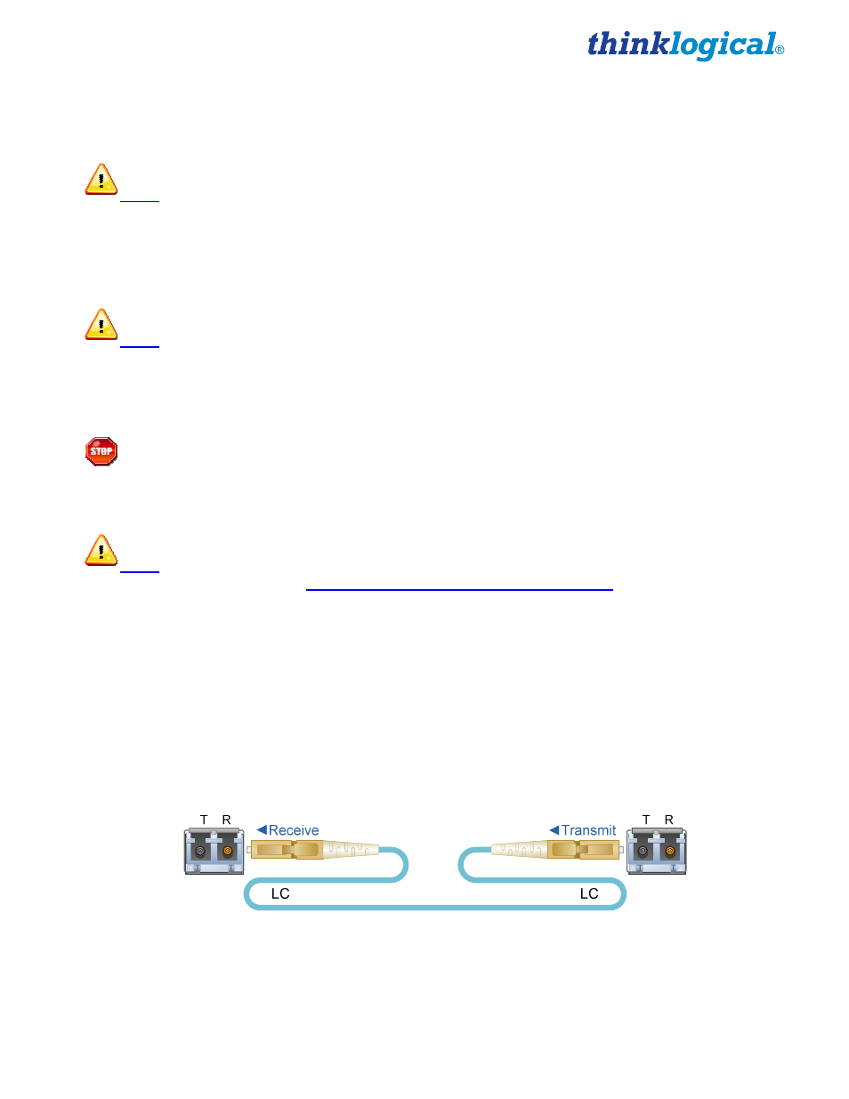
Connecting to the VX640
Fiber Optic Cable
Requirements
Thinklogical
®
recommends SX+ Laser Enhanced (50µm) fiber for your VX640 KVM Matrix Switch and
Velocity Extension System. Multi-mode fiber can extend up to a maximum of 1000m and Single-mode
fiber can extend distances beyond 1000m.
Handling Fiber Optic Cable
Unlike copper cabling, fiber optic cable requires special handling. A small speck of dust or a
scratch to the ferrule tip (the end of the connector) can attenuate the optical signal, rendering
the cable inoperable.