Quick-start guide, Transmitter side receiver side – Thinklogical Q-4300 KMASS Modules Manual User Manual
Page 29
Q
-S
e
rie
s
K
M
A
S
S
M
o
d
u
le
s
P
ro
d
u
c
t M
a
n
u
a
l
2
9
R
e
v
. B
: A
u
g
u
s
t 2
0
1
3
A
p
p
e
n
d
ix
B
- Q
-S
e
ri
e
s
K
M
A
S
S
M
o
d
u
le
Q
u
ic
k
S
ta
rt
G
u
id
e
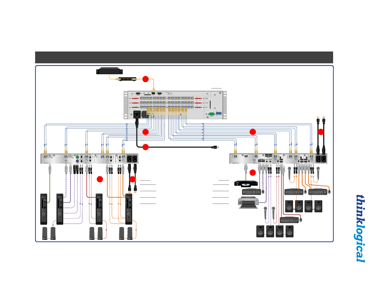
S
o
u
rc
e
C
P
U
1
Network Hub
STEP 7:
Connect the
MX
48
Controller Card’s LAN Port to your
Controller CPU with a CAT5 cable.
(CPU IP address: 192.168.13.9)
Controller Card
IP Address: 192.168.13.15
QUICK-START GUIDE
QUICK-START GUIDE
STEP 1:
Connect the Q-Series KMASS Receiver Modules to a router using
multi-mode fiber-optic cables (up to 1000 meters). Connect fiber
K1
to any
SFP’sTransmit Port and fiber
K2
to the same SFP’s Receive Port. Connect fiber
K1'
to any other SFP’s Transmit Port and fiber
K2'
to the same SFP’s Receive
Port.
STEP 2:
Ensure the Q-4300 Chassis Power Supply switches on the front panel
are in the OFF position. Install the Right Power Supply Module AC Power Cord
(Left receptacle) and the Left Power Supply Module AC Power Cord (Right
receptacle) onto the Q-4300 Chassis. Plug both AC Cords into a standard AC
source. On the front of the chassis, turn ON the Right and Left Power Supply
Modules.
STEP 3:
Connect the USB and Audio peripheral devices to the Receiver
Modules using standard copper cables as shown in the examples below. Turn all
the devices ON.
STEP 4:
Connect the Q-Series KMASS Transmitter Modules
to a router using multi-mode fiber-optic cables (up to 1000
meters). Connect fiber
K1
to any SFP’s Receive Port and fiber
K2
to the same SFP’s Transmit Port. Connect fiber
K1'
to any
other SFP’s Receive Port and fiber
K2'
to the same SFP’s
Transmit Port.
STEP 5:
Ensure the Q-4300 Chassis Power Supply switches on the
front panel are in the OFF position. Install the Right Power Supply
Module AC Power Cord (Left receptacle) and the Left Power Supply
Module AC Power Cord (Right receptacle) into the Q-4300 Chassis.
Plug both AC Cords into a standard AC source. On the front of the
chassis, turn ON the Right and Left Power Supply Modules.
STEP 6:
Connect the USB and Audio device sources from the CPU to
the Transmitters with standard copper cables. Ensure the CPUs are
turned ON.
External Control CPU
2
5
7
MX
48
Router KVM Matrix
Switch Chassis,
MXR-000048
3 Rack Units, 200 Watts
Q-Series Chassis
VQS-004300
VQM USB 2.0 Receiver
VQM-U00001-LCRX
VQM USB 2.0/USB HID/
Audio Receiver
VQM-UAP001-LCRX
VQM Redundant
USB HID/Audio Receiver
VQM-HAR001-LCRX
VQM Dual USB HID/Audio
Receiver
VQM-HA0006-LCRX
3
4
1
8
Transmitter Side
Receiver Side
Power Supply
As used with Thinklogical’s® Q-Series KMASS Modules Fiber Extension System
As used with Thinklogical’s®
Q-Series KMASS Modules
Fiber Extension System
STEP 8:
Ensure the ON/OFF switch located above the Power
Supply’s AC receptacle is in the OFF position. Connect the
supplied AC Power Cord (PWR-000006-R) to the receptacle and
plug it into a standard AC source. Turn the switch ON. Verify that
all system functions are operating properly.
K1'
K2'
K2
K1
K2
Complete Steps 1-8 to connect to a KVM Matrix Router:
6
K1
K2'
K1'
K2
K1
K2
K1
K2
K1
K1
K2
K1
K2
K1
K2
K1
K2
K1
K2
S
o
u
rc
e
C
P
U
2
S
o
u
rc
e
C
P
U
3
S
o
u
rc
e
C
P
U
4
U
S
B
2
.0
U
S
B
H
ID
*
U
S
B
2
.0
P
S
2
K
y
b
d
.*
P
S
2
M
o
u
s
e
*
L
in
e
IN
L
in
e
O
U
T
L
in
e
IN
L
in
e
O
U
T
L
in
e
IN
1
L
in
e
O
U
T
1
L
in
e
IN
2
L
in
e
O
U
T
2
U
S
B
H
ID
U
S
B
H
ID
1
U
S
B
H
ID
2
*Connect either USB HID or
PS2. If both are connected,
HID will over-ride PS2.
1
2
3
4
Q-Series Chassis
VQS-004300
VQM USB 2.0 Transmitter
VQM-U00001-LCTX
VQM USB 2.0/USB HID/
Audio Transmitter
VQM-UAP001-LCTX
VQM Redundant
USB HID/Audio Transmitter
VQM-HAR001-LCTX
VQM Dual USB HID/Audio
Transmitter
VQM-HA0006-LCTX
USB 2.0
USB HID
USB 2.0
USB HID
USB HID 1
USB HID 2
K1: Data TX to RX
K2: Data RX to TX
K1': Redundant Data TX to RX
K2': Redundant Data RX to TX
Local Audio
OUT CPU 2
Local Audio
OUT CPU 3
Local Audio
OUT CPU 4