TE Technology TC-48-20 User Manual
Page 34
34
The ALARM 2 HIGH SETTING, ALARM 2 LOW SETTING, and ALARM 2 DEADBAND function in the same manner as
described above for ALARM 1 settings except that they are referenced to the secondary sensor.
OUTPUT SHUTDOWN WITH ALARM1: if this option is turned on and an alarm condition occurs relative to the
primary sensor, then the controller will shut power off to the TE device. Power will automatically be restored if you
have the NO LATCHES option selected. If the ALARM 1 LATCH or the ALARM 1&2 LATCH option is selected, then
power will stay off, even if the alarm condition clears itself, until you click the ALARM LATCH CLEAR button.
OUTPUT SHUTDOWN WITH ALARM2: same as the OUTPUT SHUTDOWN WITH ALARM1 except as referenced to the
secondary sensor.
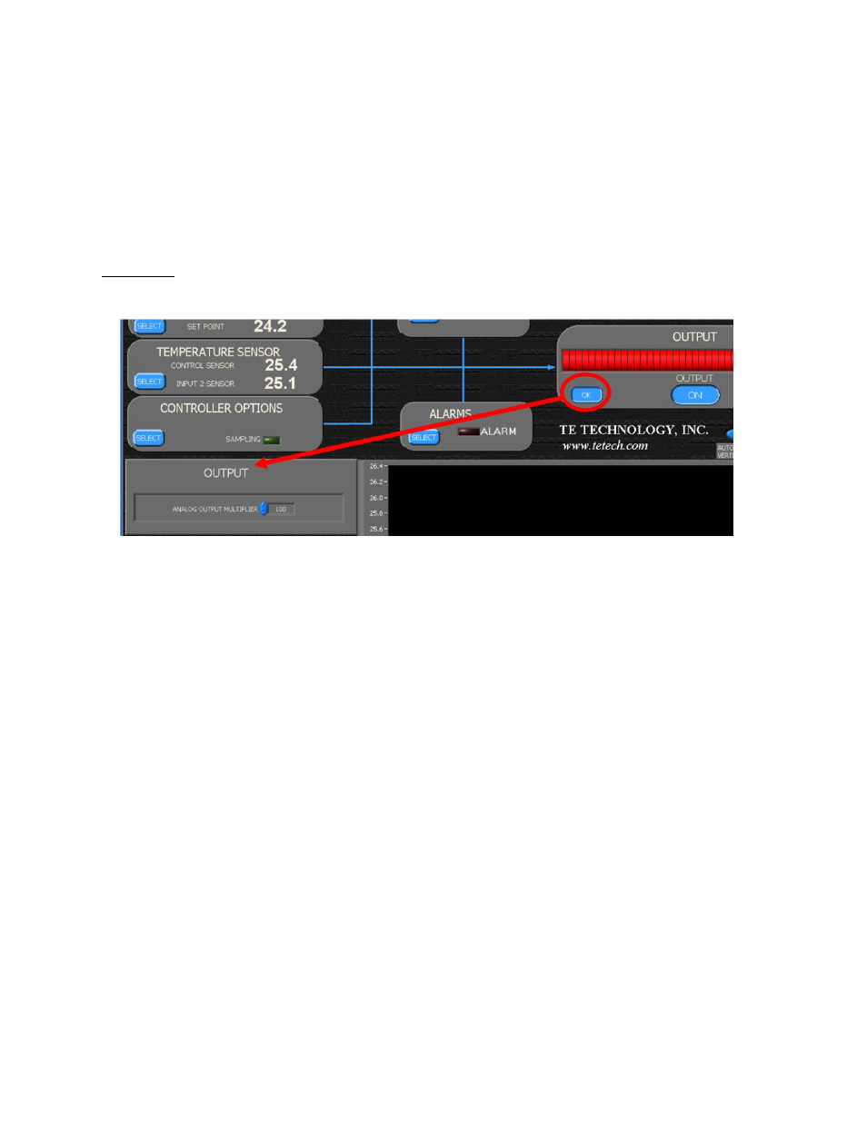
OUTPUT box
This shows the percentage of maximum power output that the controller is providing to the TE device.
The output can be turned on and off by clicking the output button either ON or OFF. Whenever a change is made
in the software, the controller is updated in real time. However, it might be beneficial to turn off the output first
and then make all of your software/controller settings before turning on the output. Be sure that the output is set
to ON prior to shutting down the software though; otherwise, if you attempt to use the controller again without
the software, you will not be able to turn the output on.
The menu provides for adjusting the analog output voltage. The analog output voltage provided by the controller
(see “Controller Schematic for further details”) is a 0‐5V DC control signal which corresponds to 0 to 100% power
output. The ANALOG OUTPUT MULTIPLIER can be set from 0 to 1. When it is set to 1, the analog output voltage
can range from 0 to 5 V. If, for example, it is set to 0.5, then analog output voltage can range from 0 to 2.5 V. This
can be useful for limiting the output voltage of power supply.