Operating instructions – TE Technology TC-48-20 User Manual
Page 13
13
Operating Instructions
1.0 Setup
1.1
Attach the thermistor at an appropriate temperature‐control location. Locating the thermistor at the cold
side of the TE device provides better control stability than locating it at the object, liquid, or air that is to be
cooled/heated. However, in doing so, there will be a temperature difference between the TE device and
the object, liquid, or air that is to be cooled/heated. The temperature set point can be adjusted to
compensate for this temperature difference if necessary.
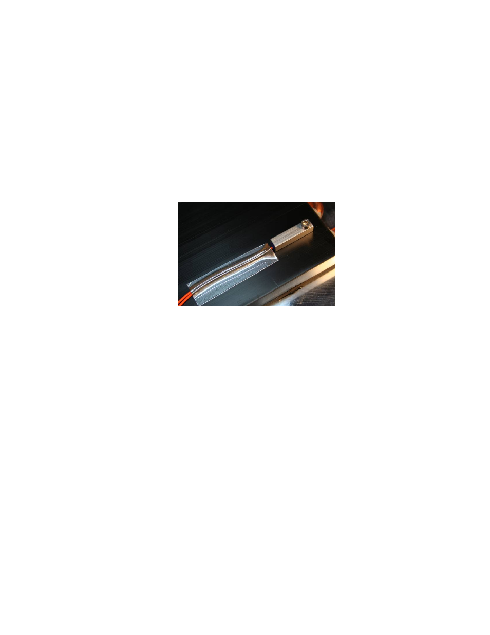
NOTE: When possible, it is recommended that at least 50 mm of the thermistor’s wire be thermally
connected to the cold side of the TE device as shown in the example below. This can be accomplished by
placing aluminum tape over the thermistor wires and adhering the wires and tape to the cold side of the
cooler, as shown below. If this is not done, the thermistor wires will be at a different temperature than the
cold side and they will add or remove heat in the region of the thermistor, making the temperature reading
significantly less accurate and thermal response time slower.
The wire leads of the thermistor can be lengthened if necessary. For longer lengths the use of twisted pair
and/or shielded wire may be required to reduce noise.
In addition, the thermistor needs to have a good thermal connection to the temperature control location.
When using the MP‐3193, thermal grease should be applied to the interface of the thermistor and
temperature‐control location. The TP‐1 thermal grease from TE Technology or other thermal grease can be
used.
The TC‐48‐20 is supplied with the MP‐3193 thermistor. Other thermistor styles directly compatible with the
controller are available as options. See “Thermistor Styles for TC‐48‐20” for reference. In addition, the
controller can be configured to use thermistors that have the same temperature‐resistance curves as the 10
k‐ohm, curve “B” thermistor from YSI Temperature, Inc. (Resistance versus Temperature curves are in
Appendix A.)
If you want to use a thermistor that has a different resistance‐temperature curve from the standard MP‐
3193 (See “Temperature versus Resistance for MP‐3193, MP‐2444, and MP‐2542 Thermistors” for
reference) or the 10 k‐ohm thermistor, it can be done as long as the operating resistance range is within
that of the standard thermistor. The thermistor must be a negative temperature coefficient device.
Because the temperature controller is really measuring the thermistor’s resistance and converting this to a
temperature, the temperature controller will be fooled into thinking that the thermistor is at a different
temperature than it really is, and the Set‐Temperature will be skewed accordingly. A loss of resolution and
control stability may occur as a result. The user assumes all risks associated with making any substitutions,
and TE Technology assumes no liability whatsoever for the operation of the controller when a non‐standard
thermistor is used.
1.2
Connect the thermistor wire leads to JP5‐1 and JP5‐2. (See “Controller Schematic” and the “Controller
Hookup” drawings for reference.)
1.3
A secondary thermistor can be connected to JP5‐3 and JP5‐4. The secondary thermistor can then used to
monitor the hot side of the TE device for determining whether the TE device has exceeded its maximum