20 2.0 display and menu options – TE Technology TC-48-20 User Manual
Page 20
20
2.0 Display and Menu Options
Note: this section applies only to the TC‐48‐20. Setup, programming, and communications with the TC‐48‐20 OEM
controller can only be accomplished by using the computer software with the optional MP‐3023 RS232 cable.
Changes made to the controller using the keypad are always stored in the EEPROM regardless of EEPROM WRITE
ENABLE setting.
2.1
Initialization screen
1. Displays for 1.5 seconds:
TE TECHNOLOGY
www.tetech.com
2. Displays for 1.5 seconds:
TE TECHNOLOGY
TC‐48‐20 Rev. ****
2.2
Primary screen
TEMP = ###.# °C
OUT = ###% T2=##
The controller displays information about the following items:
1) The temperature of the control sensor (TEMP) to a 0.1 °C resolution
2) The output level (duty cycle) to the thermoelectric modules (OUT)
3) The temperature of the second temperature sensor (T2)
If the control sensor is either an open circuit or a short circuit (indicating that the sensor is not
connected or has failed), the controller will display SENSOR 1 ERROR on the top line of the display
instead of TEMP = ###.# °C. The output % will also be forced to 0% until the error is resolved.
If a secondary sensor is not connected to the controller, T2= ### will not be displayed (unless it is
forced to display by using the software menu setting).
If ALARM 1 or ALARM 2 has caused the power output to be turned off, the words ALARM and OUT= 0% will
flash in alternating sequence in the place of the normal OUT=###% indicator. When not using a thermistor
on the second sensor input the user will need to adjust the ALARM 2 FUNCTION to KEEP OUTPUT ON.
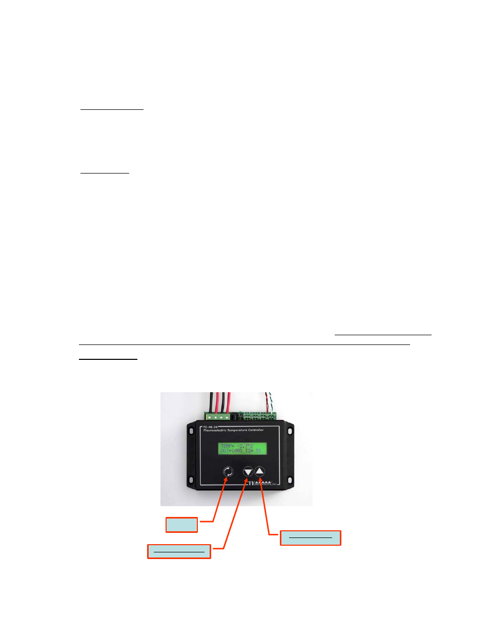
Parameters Menu
When at the Primary Screen (shown below), depressing the MENU key allows the user to scroll through and
adjust the various controller parameters.
MENU
BUTTON
DOWN ARROW BUTTON
DECREASE PARAMETER
UP ARROW BUTTON
INCREASE PARAMETER