0 tuning parameter description, Tuning parameter description – TE Technology TC-36-25-RS232 User Manual
Page 24
2.15 Review all of your controller configuration selections. If all the configuration selections are correct for your
application, click the SEND BOX VALUES button in the CONFIGURE section to download these settings to the
controller.
NOTE: Remember to click the SEND BOX VALUES button to update the controller any time CONFIGURE variables
have changed.
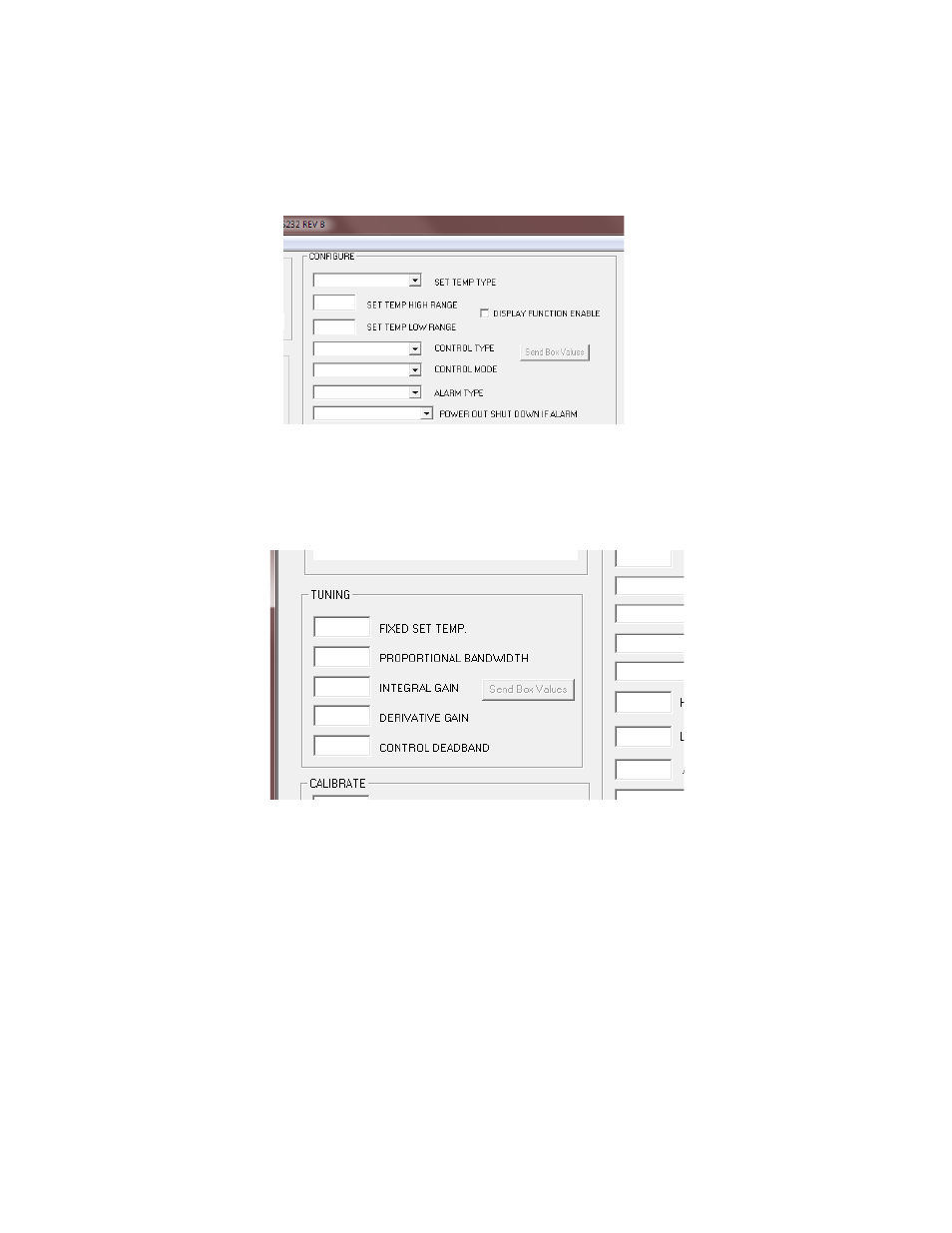
3.0 Tuning Parameter Description
3.1
In the TUNING section of the software, the various selections below are used to establish the set point and the
variables affecting set point stability.
3.2
FIXED SET TEMP. box:
a) Enter the set temperature value in degrees. This temperature must be within both the range of the selected
input sensor and the limits of low and high set ranges from the controller configuration setup. Also, verify that
the cooler is capable of safely operating at the entered set temperature. This is particularly important if you are
heating. While you can control to +100 °C using the standard thermistor, many TE devices are only rated for at
most 80 °C.
b) If you selected COMPUTER CONTROL in the CONTROL TYPE menu key under the CONFIGURE section, the values
that can be entered in the FIXED SET TEMP box range from –5.11 to +5.11. This corresponds linearly to a
fixed percentage of power output where –5.11 equals –100% power and +5.11 equals +100% power. If you
selected HEAT WP+1 and WP2- under the CONTROL MODE menu key under the CONFIGURE section, then -5.11
corresponds to full-power cooling. The value is adjustable in 0.01 unit increments.
24