Super Systems Paperless VR User Manual
Page 41
Super Systems Inc.
Page 40 Video Recorder Manual Version 2 Rev. B
video recorder datalogger, i.e. type K, type J, etc. Then, source a specific temperature, like 1000
F, or
millivolt to the connected input. It is recommended that the actual temperature used be similar to an
appropriate process temperature. For example, if your equipment normally operates at 1700
F, then
perform the cold junction calibration using a 1700
F signal. It is important to note that when performing
a zero or span calibration,
do not use
regular thermocouple wiring. Instead, use any kind of regular
sensor wire, or even regular copper wire. To perform the calibrations, the user will need a calibrator that
is capable of outputting volts, millivolts, and temperature.
Note: To check the screen version number, click on the
Status
menu option from the
Configuration
menu. The screen’s revision number will be listed next to the “Touchscreen Revision” line
. When the
Calibration
menu is first selected, the screen software must first load up the screen’s configuration
settings. When the settings have been loaded, the Calibration tab will be displayed.
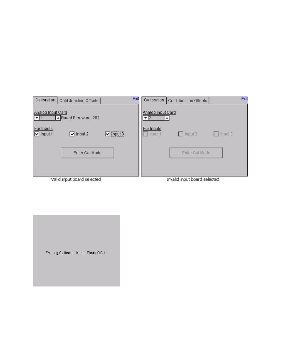
If an existing input board is selected in the “Analog Input Card” section, then that input board’s firmware
revision number will be displayed next to the input board number and the inputs to be calibrated will be
enabled (see the figure on the left above). If a non-existing board is selected, there will be no firmware
revision number shown and the inputs to be calibrated will be disabled (see the figure on the right above).
The user will be able to select boards 1 through 8. Select
the inputs to calibrate by checking the checkbox next to each
input where: check = Yes (calibrate) and no check = No (do
not calibrate). Once the inputs to calibrate have been
chosen, press the Enter Cal Mode button to begin the
calibration process.
Once the calibration screen is displayed, the drop-down list
on the left of the screen will allow the user to select either
Zero Cal or Span Cal, depending on which calibration is
desired.
The “Input Values (mV)” section will display the selected
inputs and the associated values for those inputs. If an input has not been selected from the previous
screen, that input’s value will be dashes “---”. The “Calibration Range” drop-down list will allow the user
to select the appropriate range for the thermocouples. See the
TC Type mV Range Chart
on page 35 if the
range is not known for a specific thermocouple type.