Sundance high speed bus (shb), Registers – Sundance SMT351 User Manual
Page 16
Version 1.6
Page 16 of 25
SMT351 User Manual
DDR SDRAM
32 Meg x 16 bits
16
-bi
ts
da
ta
b
u
s
DDR SDRAM
32 Meg x 16 bits
16
-bi
ts
da
ta
b
u
s
4x
co
m
po
ne
nt
s
4x
co
m
po
ne
nts
32
-bi
ts da
ta
b
u
s
Chip Enable 3
Chip Enable 2
Chip Enable 1
Chip Enable 0
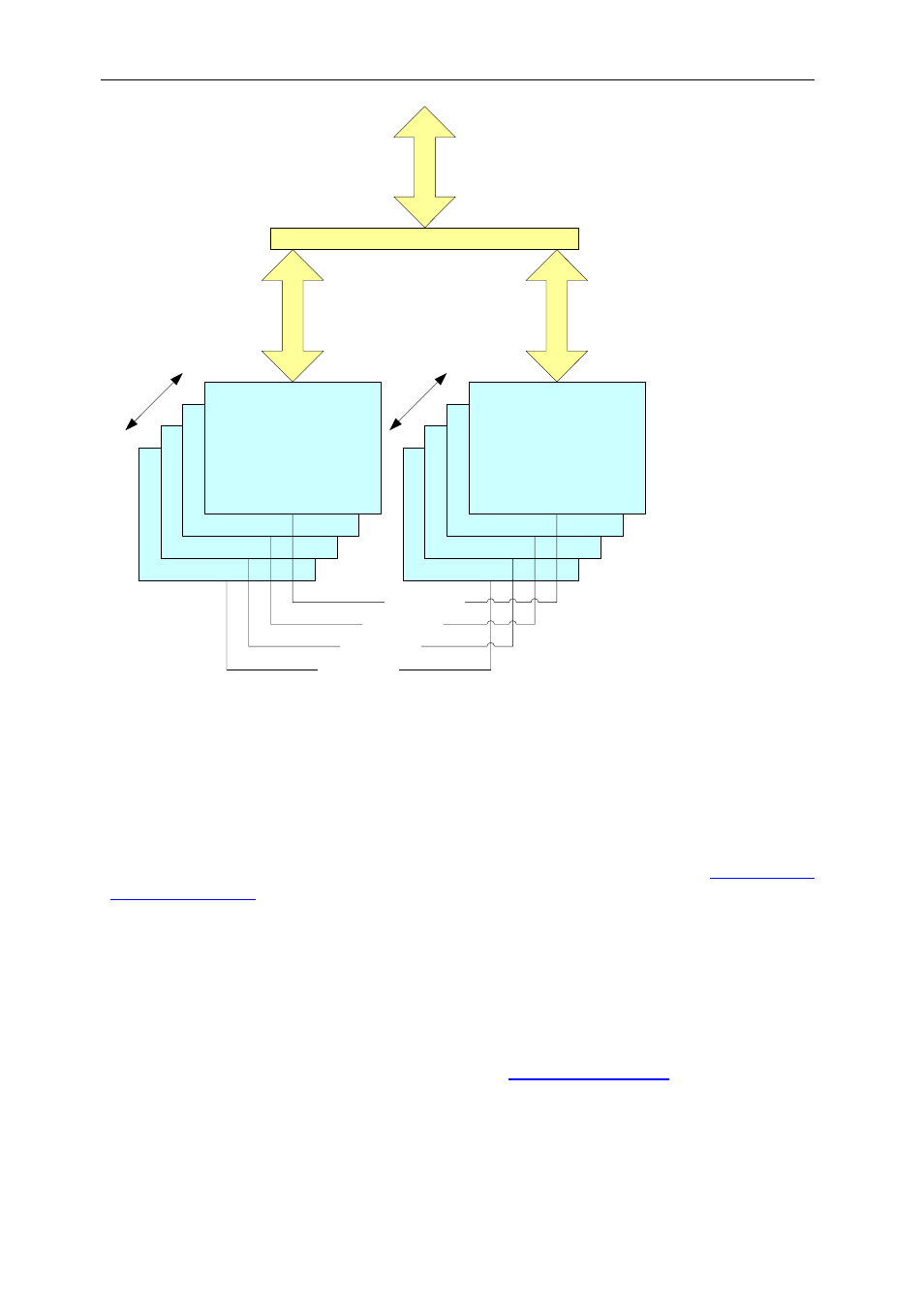
Figure 4: DDR SDRAM components compartments organization.
One compartments is made from eight 32M x 16-bits DDR SDRAM components,
each of them having a 16-bit data bus. Memory components are accessed in pairs.
Sundance High Speed Bus (SHB)
Data are input and output from SMT351 using the SHB protocol. See
SUNDANCE
SHB specification
for more details.
The SHB interfaces implemented in SMT351 are unidirectional full word (32-bits).
SHB A is a receiver-only interface and SHB B is a transmitter-only interface; both are
clocked at 100 MHz, giving a maximum data rate of 400 MB/s.
Registers
Command words can be sent over comport 3 to control the SMT351. Words received
will be written into registers in the FPGA. See
section for more
details.