Model 50 back panel model 50 front panel – Studio Technologies 50 2005 User Manual
Page 8
Issue 7, August 2005
Model 50/51 User Guide
Page 8
Studio Technologies, Inc.
Control Room Monitoring
The control room section provides two
stereo line-level outputs for driving two
power amplifiers associated with monitor
loudspeakers. Seven buttons are used to
select the input source to be monitored.
The control room level is adjusted using
a smooth-feeling rotary potentiometer. The
Dim button allows the control room level
to be temporarily reduced. The Control
Room A/B button allows the control room
A or B outputs to be activated. The Mono
button allows the sum (L+R) of the select-
ed source to be sent as the control room
output.
Meter Output
The meter output provides a stereo output
that “follows” the source selected for the
control room. The signal is not affected
by the control room level circuitry, but is
“post-mono.” The meter output is intend-
ed to be connected to VU- or PPM-type
meters or meter panels that contain series
current-limiting resistors or input buffer
amplifiers. In addition, they must support
meter calibration to ensure precision level
reading.
Studio Monitoring
The studio monitoring source is config-
ured to follow either the selected control
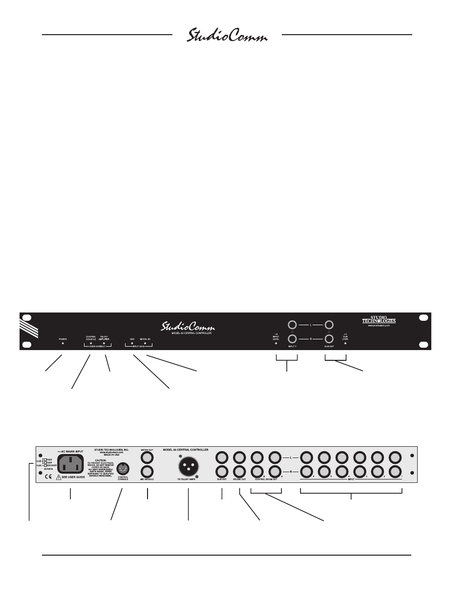
Meter output and
Mic Module input
Model 50 Back Panel
Model 50 Front Panel
Power present
LED
Stereo line input 7;
LED indicates +4 dBu
configuration
Input data
present LED
Talent Amplifier
over current LED
Dub output;
LED indicates +4 dBu
configuration
Model 51
Control Console
over current LED
Model 50
input data LED
AC mains
connection
To/from Model 51
Control Console
Output to talent
amplifiers
Control room
A & B outputs
Studio output
Mains voltage
configuration
chart
Stereo line
inputs 1-6
Dub
output