Studio Technologies 50 2005 User Manual
Page 14
Issue 7, August 2005
Model 50/51 User Guide
Page 14
Studio Technologies, Inc.
by Model 50 circuitry. While 1%-tolerance
resistors are used in the Model 50, the
meters or meter panels should include
calibration trim pots to ensure the most
accurate level reading.
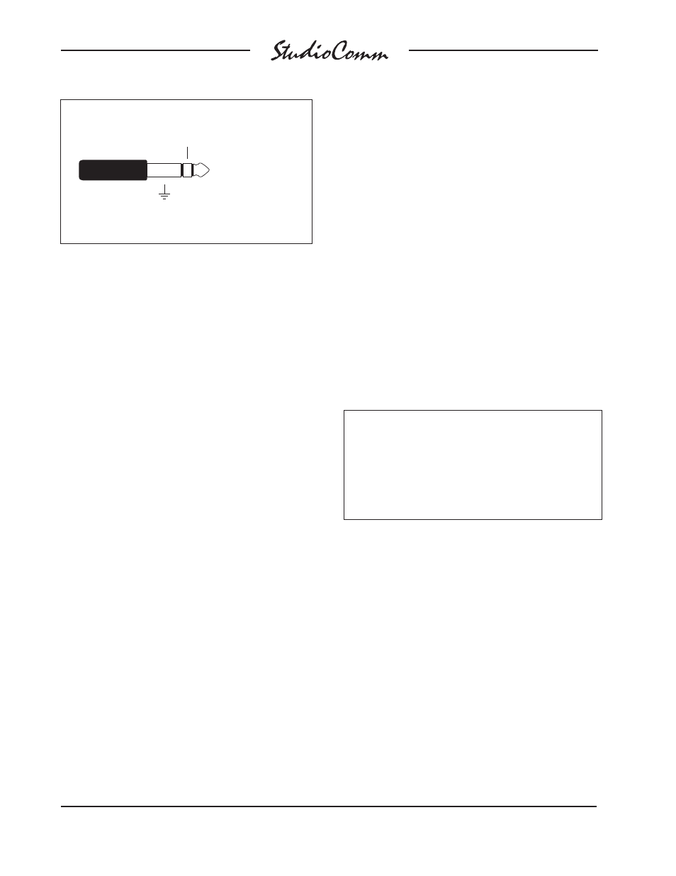
A single ¼-inch 3-conductor jack is used
to connect to the stereo meter output.
Each output channel is unbalanced, has
a nominal level of +4 dBu, and is capable
of driving loads of 2 k ohms and greater. A
¼-inch 3-conductor plug should be wired
with tip for the left output, ring for the right
output, and sleeve for common.
Mic Module Input
A ¼
-inch 3-conductor phone jack, labeled
Mic Module, is located on the back panel.
In most cases the Mic Module input will
not be used, and no plug should be insert-
ed. For details on using the Mic Module
input, refer to the Advanced Installation
Topics section later in this guide.
Talent Amplifier Output
Up to four Model 35 Talent Amplifiers can
be connected in any combination to the
Model 50’s talent amplifier output. The
output connector is a 3-pin male XLR-
type. For best performance, use low-
capacitance shielded microphone-type
cable to distribute the talent amplifier
signal. If you have a choice, select cables
with the heaviest wire gauge commonly
available. This will reduce voltage drop
when using long cable runs. Refer to the
Technical Notes section for additional infor-
mation.
The simplest installation would use a
microphone cable to connect the Model 50
to the first talent amplifier; the loop through
connector on that talent amp sending the
signal on to the next talent amp.
For convenience, you may want to wire
your facility to allow easy access to the
talent amplifier signal at all locations
where talent amplifiers might be used.
The talent amplifiers connect to the Model
50 in parallel, so the connectors on the
distribution panels or mult boxes must
be wired in parallel.
Warning: Do not connect the Model 50’s
talent amplifier output to anything but
Studio Technologies’ talent amplifiers.
Some audio equipment may be dam-
aged by the +23 Vdc contained on pin 2
of the talent amplifier output connector.
Several mounting options are available for
the Model 35 Talent Amplifier. For details
refer to the Mounting Options sections in
the Advanced Installation Topics section
of this user guide.
In special cases you may need to obtain
a stereo, balanced line-level output signal
from the Model 50 talent amplifier output.
The Model 70 Interface is available for this
purpose. For details refer to the Advanced
Installation Topics section later in this
guide.
Meter Output
Sleeve: Common
Tip: Left output
Ring: Right output
(Switchcraft No. 297, Neutrik NP3C, or equivalent)