5) motor and blower wheel check, 0) installation data – Space Ray LTS Series Two Stage User Manual
Page 56
Form #43155040
May 2013
-55-
IGNITION MODULE DIAGNOSTICS
IGNITION MODULE DIAGNOSTICS
IGNITION MODULE DIAGNOSTICS
IGNITION MODULE DIAGNOSTICS
(Fenwal #35
(Fenwal #35
(Fenwal #35
(Fenwal #35----6087J1
6087J1
6087J1
6087J1----034 module only)
034 module only)
034 module only)
034 module only)
The LED
LED
LED
LED located on the ignition module will flash ON
ON
ON
ON for ¼ second, then OFF
OFF
OFF
OFF for ¼ second during a fault
condition. The pause between fault codes is 3 seconds.
LED Indication
Error Mode
Steady On
Internal Control Fault
2 Flashes
Flame Sense Fault
3 Flashes
Ignition Lockout
TO CHECK FLAME SENSOR CIRCUIT
TO CHECK FLAME SENSOR CIRCUIT
TO CHECK FLAME SENSOR CIRCUIT
TO CHECK FLAME SENSOR CIRCUIT
(Fenwal #35
(Fenwal #35
(Fenwal #35
(Fenwal #35----6087J1
6087J1
6087J1
6087J1----034 module only)
034 module only)
034 module only)
034 module only)
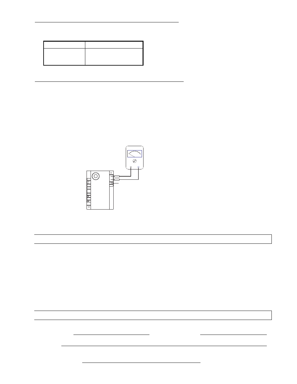
The flame current is the current that passes through the flame from the sensor to the ground. The
minimum flame current necessary to keep the system from lockout is 0.7
0.7
0.7
0.7 micro-amps.
a.
To measure the flame current, connect an analog DC micro-ammeter to the FC
FC
FC
FC---- and FC+
FC+
FC+
FC+ terminals per
diagram. The meter should read 0.7
0.7
0.7
0.7 micro-amps or higher when the burner is running full on.
b.
If the meter reads below zero
zero
zero
zero, the meter leads are reversed. Disconnect power and reconnect the meter
leads for proper polarity.
c.
Remove micro-ammeter. Return system to normal operation.
MULTIPURPOSE METER
USE
MICROAMP
SCALE
BLACK (-)
RED (+)
LED Display
VALVE
GND
(BURNER)
FC-
FC+
VALVE
25V
Ignition Module - Alternate
(Fenwal #35-6087J1-034)
24.5)
MOTOR AND BLOWER WHEEL CHECK
If draft inducer motor fails to run:
a.
Check power supply to junction box.
b.
Check for loose or broken motor lead wire.
c.
Check to see that blower wheel turns freely and is not rubbing housing. Blower wheel may have worked
loose from shaft and jammed against housing.
d.
Check for blower wheel damage; replace if necessary. If no damage, readjust blower wheel on shaft &
retighten set screw.
e.
If all above does not correct, replace motor.
25.0)
INSTALLATION DATA
Date of
Installation:
# of Heaters in
System:
Serial No.
Model:
LTS
LTS
LTS
LTS or
or
or
or LTU
LTU
LTU
LTU
N = Natural Gas
L = Propane Gas