Space Ray LTS Series Two Stage User Manual
Page 14
Form #43155040
May 2013
-13-
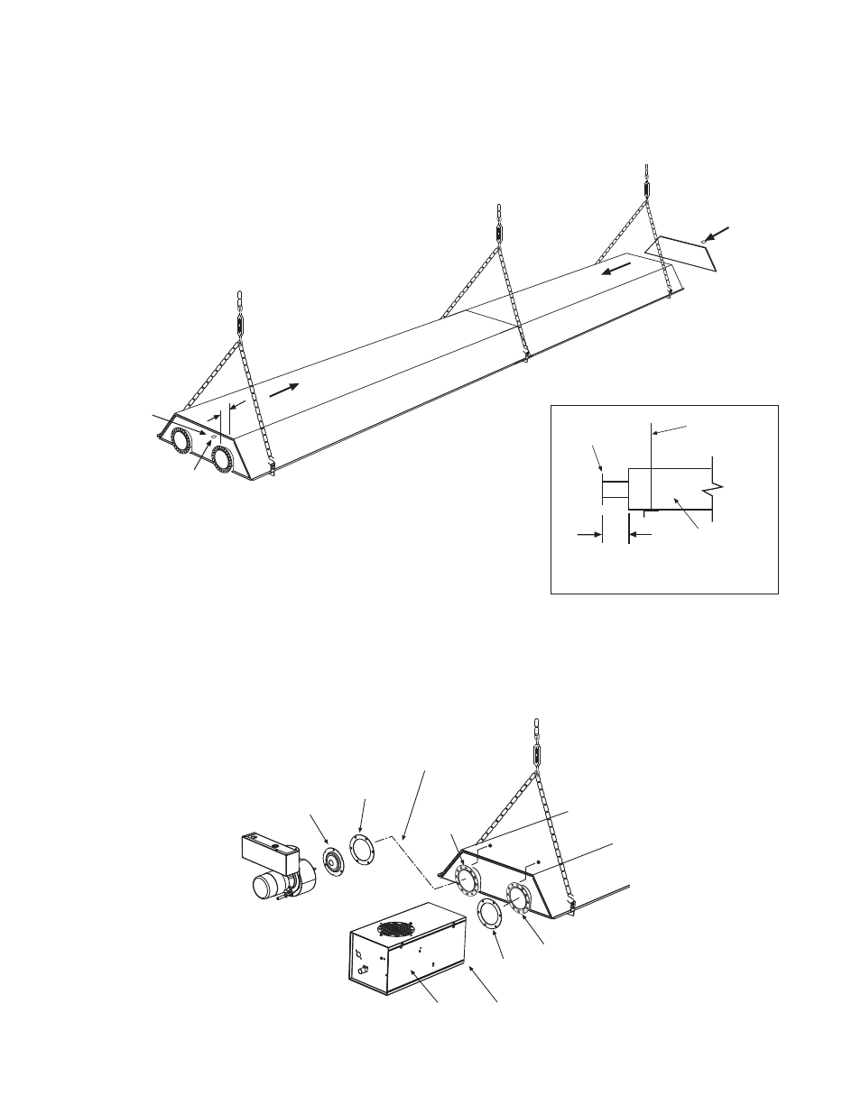
3.
Assembly the reflectors onto the body section. Leave 3” space between the tube flange and the first
reflector for later mounting of control box and draft inducer.
4.
Place the flanges of the control end reflector flush with the end of the first reflector. Secure by sliding
speed clips onto reflector edges. Evenly space 6 speed clips on sides and top of reflectors to provide a
snug fit. Place foot end reflector on the opposite end of the reflector and secure as above.
Tube Flange
Side View
Suspension
chain
reflector
3
4
3
3
4
Speed
Clip
3
5.
Attach the control box to the right-hand control tube flange and secure with 1/4-20 locknuts. The control
box must be mounted with the perforated fresh air plate on top, facing the ceiling.
6.
Attach the draft inducer assembly to the left-hand draft inducer tube flange and secure with 1/4-20
locknuts. A flue restrictor plate is attached to the draft inducer weld studs. DO NOT DISCARD
DO NOT DISCARD
DO NOT DISCARD
DO NOT DISCARD
RESTRICTOR PLATE
RESTRICTOR PLATE
RESTRICTOR PLATE
RESTRICTOR PLATE and make sure this remains in place while the draft inducer is being attached to the
heater body.
1/4-20
Locknuts
Tube Flange
(control)
Gasket
Access
Panel
Control Box
Draft Inducer
(vertical position)
Flue Restrictor
Plate
Do Not Discard.
Gasket
6
Tube Flange
(draft inducer)
5