8) lts series - attaching draft inducer assembly – Space Ray LTS Series Two Stage User Manual
Page 28
Form #43155040
May 2013
-27-
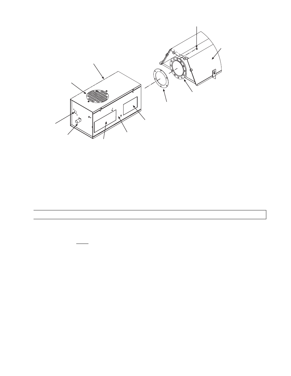
Tube Flange
12 Radial Hole for 40-200M BTU units only
6 Hole for 225-250M BTU units only
MPT Gas
Pipe Connection
Reflector
1/4-20 Locknut
(QTY-3 per flange)
Tube Flange
Gasket
3/8 Connector
(24V wire leads from
draft inducer to
L1 and L2 of the
control box terminal block)
Control Box
Perforated
Fresh Air Plate
Burner
Sight Glass
Nameplate/
Rating Label
Clearances to
Combustibles
Label
Access
Panel
Note: The wiring connection
diagram is located on the inside
access panel and inside the
junction box panel.
4.
The heater can be mounted horizontally
horizontally
horizontally
horizontally or at an angle of up to 45 degrees
45 degrees
45 degrees
45 degrees maximum from horizontal.
When angle mounting, the control box
control box
control box
control box must be positioned upright
upright
upright
upright. F
F
F
Failure to install the control box in an
ailure to install the control box in an
ailure to install the control box in an
ailure to install the control box in an
upright position will VOID the manufacturer
upright position will VOID the manufacturer
upright position will VOID the manufacturer
upright position will VOID the manufacturer’s warranty
’s warranty
’s warranty
’s warranty.... For additional instructions see Section 13.0) for
multiple hanging and draft inducer positions.
11.8)
LTS SERIES - ATTACHING DRAFT INDUCER ASSEMBLY
1.
Attach the draft inducer assembly and gasket to end of the draft inducer flange and secure with 1/4-20
locknuts. A flue restrictor plate is attached to the draft inducer weld studs. DO NOT DISCARD
DO NOT DISCARD
DO NOT DISCARD
DO NOT DISCARD
RESTRICTOR PLATE
RESTRICTOR PLATE
RESTRICTOR PLATE
RESTRICTOR PLATE and make sure this remains in place while the draft inducer is being attached to the
heater body. NOTE:
NOTE:
NOTE:
NOTE: The draft inducer can be mounted in a vertical, a 45º, or a horizontal position. Refer
to Section 13.0).
2.
Disconnect the piece of SJO cable (if equipped) from the junction box and discard. This is used only on
LTU series heaters.
3.
The 3/8" connector used to hold the SJO cable will remain to provide strain relief for field wiring of the
control box and the draft inducer (refer to the Electrical Connections and Connection Wiring Diagram for
wiring between the control box and the draft inducer in Section 16.0).
4.
If the heater is to be VENTED to the outside of the building, place the starting collar on the outlet of the
draft inducer and secure with the #8-32 screws and nuts. Place the flue pipe directly onto the starting
collar, secure with the #8 sheet metal screws, and terminate with an approved vent cap.
5.
If the heater is for UNVENTED use, place the exhaust hood (supplied as an accessory) directly onto the
outlet of the draft inducer (starting collar is not necessary for unvented use). Secure with the #8 sheet
metal screws. The exhaust hood must be mounted only in an upright position and directed toward the
The exhaust hood must be mounted only in an upright position and directed toward the
The exhaust hood must be mounted only in an upright position and directed toward the
The exhaust hood must be mounted only in an upright position and directed toward the
reflector body.
reflector body.
reflector body.
reflector body.