9) lts series - inclined mounting instructions – Space Ray LTS Series Two Stage User Manual
Page 29
Form #43155040
-28-
May 2013
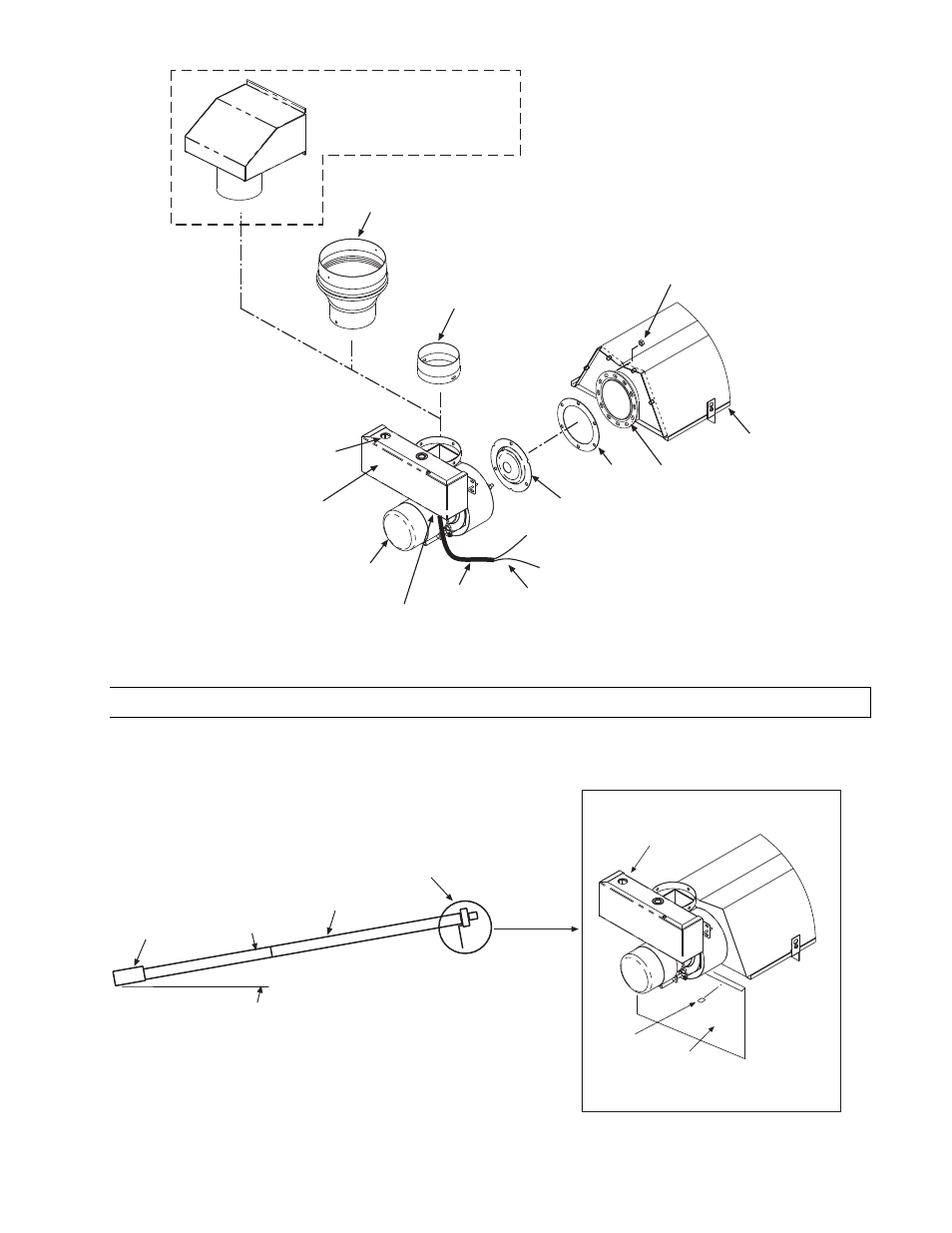
Heater Body
1/4-20 Locknut
(QTY-3 per flange)
Tube Flange
12 Radial Hole
Note: The wiring connection
diagram is located on the inside
access panel and inside the
junction box panel.
Tube Flange
Gasket
Exhaust Hood
(no starting collar necessary)
-Required for UNVENTED use-
4 x 6 Flue Pipe
Starting Collar
(for 180-250m BTU units only)
Flue Restrictor
Plate
Opening for
Electrical
Connection
Junction
Box
Draft Inducer
Wire Leads
(to L1 and L2 of the
control terminal
block)
4 Dia. Flue Pipe
Starting Collar
(for 40-175m BTU units only)
SJO Cable
3/8
Connector
11.9)
LTS SERIES - INCLINED MOUNTING INSTRUCTIONS
These inclined mounting instruction relate to LTS series heaters (straight tubes) that do not utilize the elbow
accessory. These heaters have been tested and design certified by the CSA for 2”/12” pitch (10º) inclined
mounting of the heater from the control box to the draft inducer assembly as shown in the following diagram.
Speed Clips
Inclined Mounting
Reflector
Draft Inducer
Assembly
DETAIL A
These parts are included in the inclined mounting kit.
10 Deg.
Control
Box
Body Sections
Draft
Inducer