Space Ray LTS Series Two Stage User Manual
Page 24
Form #43155040
May 2013
-23-
4.
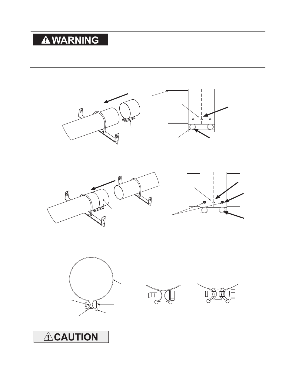
Join the body sections together and secure with tube couplings as follows:
T
TT
The following
he following
he following
he following coupling
coupling
coupling
coupling tightening
tightening
tightening
tightening instructions MUST
instructions MUST
instructions MUST
instructions MUST be
be
be
be
followed properly to ensure the integrity of the tube
followed properly to ensure the integrity of the tube
followed properly to ensure the integrity of the tube
followed properly to ensure the integrity of the tube
connections. Two #10 self
connections. Two #10 self
connections. Two #10 self
connections. Two #10 self----drilling screws
drilling screws
drilling screws
drilling screws MUST
MUST
MUST
MUST be installed
be installed
be installed
be installed
at every coupling as shown in the instructions below. Failure
at every coupling as shown in the instructions below. Failure
at every coupling as shown in the instructions below. Failure
at every coupling as shown in the instructions below. Failure
to do so may result in serious injury or property damage.
to do so may result in serious injury or property damage.
to do so may result in serious injury or property damage.
to do so may result in serious injury or property damage.
a)
Place the compression coupling over the end of the tube.
b)
Use the small hole at the centerline of the coupling to check that the coupling is inserted correctly.
c)
Partially tighten the bolt nearest the end of the tube (approximately half closed).
Tube
Coupling
1
Center end of
Tube with hole
Partially tighten this bolt
Tube
2
3
d)
Slide the next tube into the coupling.
e)
Make sure both tube ends are butted together.
f)
Finish tightening both bolts to 40-60 ft.lbs. torque to ensure a complete seal.
g)
Use the two Self-drilling screws through the pre-punched holes to secure the tubes in the coupling.
Tube
Coupling
Center both
tubes with hole
#10 Self-Drilling
Screws
(QTY 2)
4
5
7
6
h)
Check to ensure that the hardware is completely closed and the band is seated on the reaction block
and interference pins as illustrated above.
i)
Once all the heater body sections are attached, make sure that the heater system is level. If it is not,
slight adjustments can be made using the turnbuckles. (See Section 5.0)
INCORRECT
INSTALLATION
CORRECT
INSTALLATION
Force
Bars
Reaction
Block
Interference
Pins
Bolt
Band
Important:
Important:
Important:
Important: NEVER
NEVER
NEVER
NEVER reuse a coupling
reuse a coupling
reuse a coupling
reuse a coupling.... Always install a new coupling only and
Always install a new coupling only and
Always install a new coupling only and
Always install a new coupling only and
torque as per instructions above and the diagrams above.
torque as per instructions above and the diagrams above.
torque as per instructions above and the diagrams above.
torque as per instructions above and the diagrams above.