Wiring projector control, Rs-232, Wired remote/ir – SP Controls SmartPanel User Manual
Page 63: Current sensor (optional)
SmartPanel Configuration and Installation Guide
Page 59
© 2002-8 SP Controls, Inc. 930 Linden Avenue South San Francisco CA 94080
w
ww.spcontrols.com
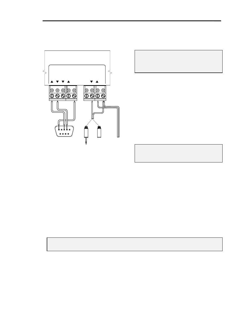
Wiring Projector Control
Note: The projector control that must be wired
for your installation depends on the
projector and your configuration, as
discussed in Control Wiring.
RS-232
The actual wiring of RS-232 varies based on
projector. Figure 29 shows one example RS-
232 connection.
The Projector Driver Application Note for
each projector specifies its RS-232 pinouts.
Aspects that can vary are connector type and
gender, RX and TX swapping, RTS-CTS use
or looping, and DSR-DTR looping.
Wired Remote/IR
Note: The ring of each IR/Wired Remote plug
or jack must be connected to the GND
terminal on the Panel.
When using the included IR emitter instead of
wired remote, attach a female 1/8” mini-jack
(not included) to the cable at the projector end, rather than splicing the emitter cable.
Using an intermediate female 1/8” mini-jack:
x
makes reversing the polarity going to the IR emitter difficult, and
x
allows the projector to be for removed without the emitter having to be pulled off the IR
window.
Current Sensor (optional)
If you are using a third-party current sensor, ensure that it provides simple closure to indicate
projector power status. Wire this closure output to the Panel pin labeled SENSE and ground to
the pin labeled GND.
Note: Most third-party current sensors require calibration to correctly identify the on and off states
of your projector. Refer to the documentation for your sensor for details.
PROJECTOR CONTROL
RS232
IR/SERIAL
RX
GND
CTS
RTS
TX
+
12V
GND
IR/SER
SENSE
1/8" mini male
(usu. to Wired
Remote port)
1/8" mini
female (usu.
for IR Emitter)
OR
To current
sensor (if
used)
To projector control port
(RS-232 pinouts vary)
Figure 29: Wiring projector control