7setting up the system – Denon AVR-5800 User Manual
Page 16
16
7
SETTING UP THE SYSTEM
• Once all connections with other AV components have been completed as described in “CONNECTIONS” (see pages 6 to 13), make the
various settings described below on the monitor screen using the AVR-5800’s on-screen display function.
These settings are required to set up the listening room’s AV system centered around the AVR-5800.
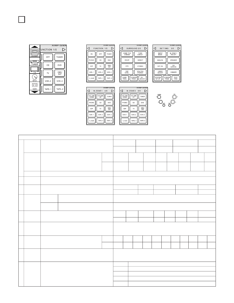
• Use the following buttons to set up the system:
• System setup items and default values (set upon shipment from the factory)
System setup
Default settings
q
w
t
y
u
i
o
Speaker
Configuration
(Surround
Speaker
Setting)
Subwoofer mode
SB CH Auto
Flag Detect
Channel
Level
Subwoofer
Peak Limit
Lev
Digital In
Assignment
On Screen
Display
Auto Tuner
Presets
Input the combination of speakers in your system and their
corresponding sizes (SMALL for regular speakers, LARGE for full-
size, full-range) to automatically set the composition of the signals
output from the speakers and the frequency response.
Use this function when using multiple surround speaker
combinations for more ideal surround sound. Once the
combinations of surround speakers to be used for the
different surround modes are preset, the surround
speakers are selected automatically according to the
surround mode.
This selects the subwoofer speaker for playing deep bass signals.
Set the method of playing the surround back channel for digital
signals.
This adjusts the volume of the signals output from the speakers and
subwoofer for the different channels in order to obtain optimum
effects.
This parameter is for detecting the maximum level of the low bass
signals output from the subwoofer channel in order to protect the
subwoofer from damage and prevent unpleasant distorted sounds
from being produced.
This assigns the digital input jacks for the different input
sources.
This sets whether or not to display the on-screen display that
appears on the monitor screen when the controls on the remote
control unit or main unit are operated (from MONITOR 1 outputs
only).
FM stations are received automatically and stored in the memory.
Surround
mode
Surround
speaker
Input
source
Digital
Inputs
Front Sp.
Small
Center Sp.
Surround Sp.
Sub Woofer
Small
Small
Yes
DOLBY/
DTS
SURROUND
THX
SURROUND
WIDE
SCREEN
5CH/7CH
STEREO
DSP
SIMULATION
EXT. IN-1
EXT. IN-2
—
A
A
A
A
A
A
A
—
LFE —THX—
Front L & R
Center
Surround L & R
Sub Woofer
12 ft (3.6 m)
12 ft (3.6 m)
10 ft (3.0 m)
12 ft (3.6 m)
Front L
Front R
Center
Surround
R
Surround
Back R
Subwoofer
0 dB
0 dB
0 dB
0 dB
0 dB
0 dB
Peak Limitter = OFF
CD
DVD
VDP
TV
DBS/SAT
VCR-1
VCR-2
TAPE-2
COAXIAL
1
COAXIAL
2
COAXIAL
3
OPTICAL
1
OPTICAL
2
OPTICAL
3
OPTICAL
4
OPTICAL
6
On Screen Display = ON
A1 ~ A8
B1 ~B8
C1 ~C8
D1 ~D8
E1 ~E8
87.5/89.1/98.1/107.9/90.1/90.1/90.1/90.1 MHz
520/600/1000/1400/1500/1710 kHz/90.1/90.1 MHz
90.1 MHz
90.1 MHz
90.1 MHz
Surround Back Sp.
Small / 2spkrs
Auto Flag Detect Mode = OFF
e
Delay Time
This parameter is for optimizing the timing with which the audio
signals are produced from the speakers and subwoofer according to
the listening position.
SBL & SBR
10 ft (3.0 m)
r
Multi Zone
Control
This sets the output level for the multi-zone 1
output jacks.
Variable
Surround
Back L
0 dB
Surround
L
0 dB
Multi Zone-1
vol. Level
Power AMP
Assignment
Set this to switch the surround back channel’s
power amplifier for use for multi-zone 2.
Surround Back
TAPE-1
OPTICAL
5
Screen while icons are displayed
Transmission codes
of independent buttons
CHANNEL• : Tuner preset
CHANNELª : Tuner preset
VOL•
: Main volume of AV amplifier
VOLª
: Main volume of AV amplifier
MUTE
: Muting of AV amplifier
VCR-3
OFF
V. AUX
OFF