Fig#2, Testing the system – Skutch Electronics CK-1R3 User Manual
Page 2
Page 2 of 4
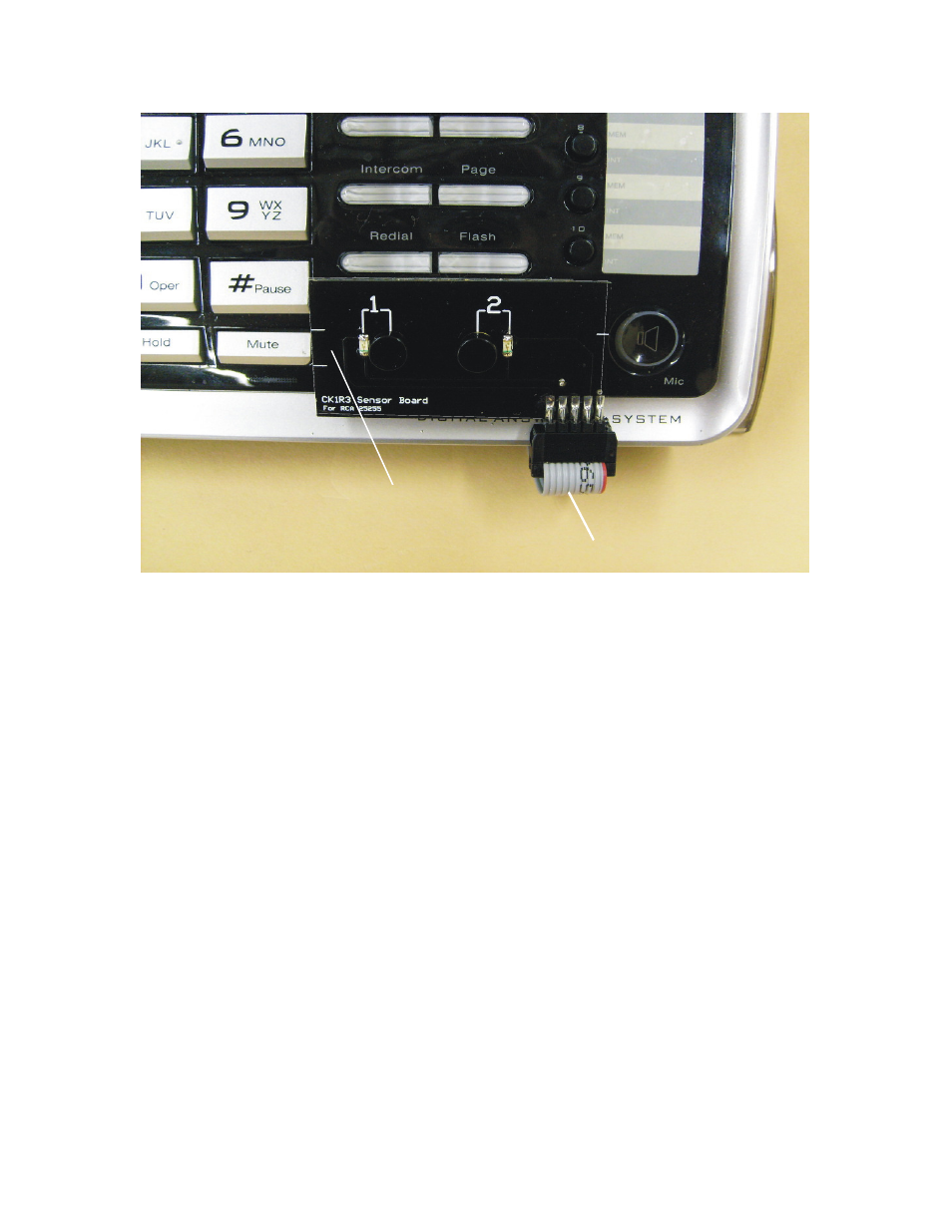
Align white lines to “Mute” button
Run Flat Cable underneath phone
Fig#2
3- Connect the supplied modular cord to [1&2 Phone] on CK-1, and the other end to the
jack [LINE 1+2] on the Phone.
4- Connect the audio cord from your audio source, to the AUDIO IN jack on the back of
the CK-1 black box where it says Audio In.
5- Run the Flat Gray Sensor Board cable underneath the base phone. Make sure that the
surface area of the base phone, where the sensor board is to be mounted, is clean and free
of all dust and oil film. Peel off the paper protector from the bottom of the sensor board,
and carefully place it OVER the LINE 1 and LINE 2 buttons on the RCA phone as shown
in Fig #2. Make sure that you align the Sensor Board to the "Mute" button on phone as
shown in Fig #2.
6- Connect the POWER CUBE from the CK-1 Black Box to 115VAC power. That's it!
Testing the System:
1- Pickup the handset and depress the line 1 button on your telephone. The No."1" Green
LED on the CK-1R3 Sensor Board should light up.
2- Repeat this test for line 2. If both lines light up when picked up, the CK-1 Sensor
Board is mounted correctly. If either light does not light up, then