Thermocouple and dc voltage – Sensoray 518 User Manual
Page 42
41
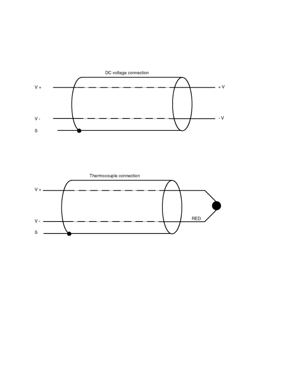
Thermocouple and DC Voltage
Thermocouples and DC voltages are connected directly to the V+ and V- terminals.
Thermocouples and DC voltage sources should not be connected to the I+ or I- terminals.
Thermocouple wires are color coded to indicate polarity. The positive thermocouple wire should
always be connected to the V+ terminal, and the negative thermocouple wire should always be
connected to the V- terminal. Please note that the red thermocouple wire is always negative, by
convention.
Electrical noise is often present on thermocouple and voltage signals. It is not within the scope of
this manual to discuss all treatments of such noise, however, a few simple techniques are
available which will solve most noise problems. The following rules apply to both thermocouple
and DC voltage channels:
1. Look at the sensor signal with an oscilloscope and DVM to see if you have the signal you
think you have. “Noise” can often be the result of an incorrect sensor installation.
2. Install the 7409TC hardware filter jumper on the offending channel.
3. Ground the “hot” end of the thermocouple. Sometimes the thermocouple is not referenced to
the PC104 return. Noise induced into the thermocouple wire from the environment can
elevate common mode voltage beyond the coprocessor input range. Make sure that the ground
is referenced to the PC104 bus ground. In the case of a DC voltage source, try grounding
either the V+ or V- signal (but not both) to limit the common-mode voltage.
4. Invoke the channel software filter.