Removal and replacement – Scotsman CU0415 User Manual
Page 27
Service Manual for Models CU0415, CU0715 and CU0920
August 2013
Page 26
Removal and Replacement
Bin Thermostat
1. Disconnect electrical power.
2. Remove front panel.
3. Remove top panel.
4. Remove left side panel.
5. Remove tape covering cap tube and pull cap tube
out of the sensing tube.
6. Remove back cover of control box.
7. Remove bin thermostat from control box and
disconnect wires from it.
8. Remove sheet metal air baffle from in front of
compressor.
9. Pull cap tube and bin thermostat from unit.
10. Route new bin thermostat’s cap tube thru notch in
left side of unit and up to the hole in the left side of
the bin.
11. Insert cap tube into sensing tube.
12. Connect wires to bin thermostat.
13. Mount bin thermostat to control box.
14. Reinstall air baffle and control box back.
15. Reinstall left side panel. Be sure master switch is
in the ON position.
16. Reinstall all panels.
17. Reconnect electrical power.
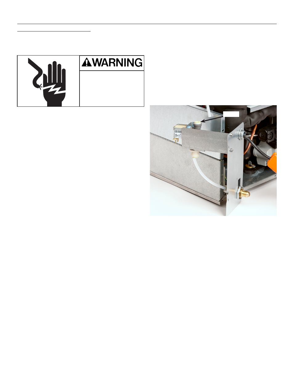
Inlet Water Solenoid Valve
1. Disconnect Electrical Power
2. Pull unit out to get back access.
3. Remove front panel.
4. Remove top panel.
5. Remove right side panel.
6. Remove back panel.
7. Shut water off to unit.
8. Remove utility panel, lower left corner viewed from
the back. Valve bracket is attached to panel.
9. Locate inlet water solenoid valve.
10. Push in collets to release inlet and outlet tubing
connections.
11. Disconnect electrical wires from valve.
12. Remove two screws holding valve to bracket and
pull valve from unit.
13. Reconnect inlet and outlet tubing by pushing them
into the replacement valve until they bottom out.
14. Re-attach wires to valve.
15. Re-attach valve to bracket.
16. Switch water on and check for leaks. Correct as
needed.
17. Reconnect electrical power and confirm no leak
while water valve is on.
18. Return all parts to their original positions.
Collet
Electrical Shock Hazard
Disconnect electrical
power before beginning