Cp 3096h back panel, Cont interface, Dial switch – RGBLink CP 3096H User Manual User Manual
Page 25: Hardware orientation, Cont interface 1: dial switch
2. Hardware Orientation
CP 3096H Back Panel
CP 3096H User Manual 25
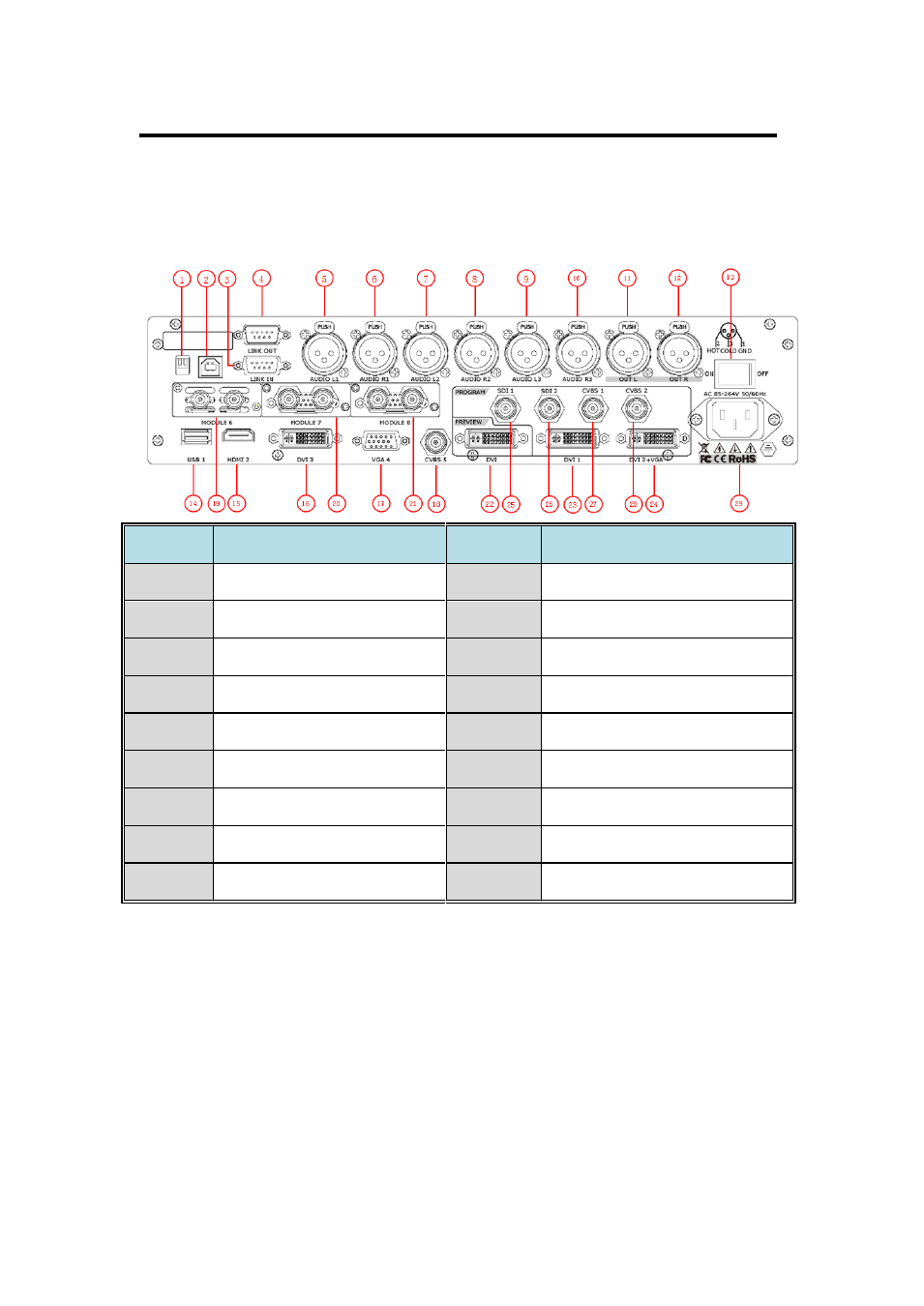
The figure below illustrates the professional interface and control signals of
CP 3096H back panel.
NO
INTERFACE
NO
INTERFACE
1
Dial Switch
17
VGA input DSUB15 port
2
USB Interface
18
CVBS input BNC port
3. 4
RS-232 Interface
19~21
S. H. D. U. V. C optional module
5~10
Audio input port
22
DVI preview output DVI-I port
11. 12
Audio output port
23
DVI output DVI-I port
13
Switch
24
DVI+VGA output DVI-I port
14
USB input USB-B port
25. 26
3G-SDI output BNC port
15
HDMI input HDMI-A port
27. 28
CVBS output BNC port
16
DVI input DVI-I port
29
Power IEC-3
CONT Interface
1: Dial Switch
If the two dial switches are upwards, the device is in normal work, and if
they are downwards, the device is in upgrade state. OLED module light is
off when the device is in upgrade state. Some of the button lights turn on,
and the device will not work.
- Driver 2A Quick Start (2 pages)
- VSP 112U (15 pages)
- VSP 112U (108 pages)
- VENUS X1 Quick Start (19 pages)
- Driver User Manual (44 pages)
- New Driver Quick Start (22 pages)
- New Driver 2 User Manual (50 pages)
- MVP 320 Quick Start (2 pages)
- New Driver 2 Quick Start (27 pages)
- MSP 215A (6 pages)
- MSP 204 Quick Start (2 pages)
- MVP 320 User Manual (60 pages)
- VENUS X1 User Manual (135 pages)
- MSP 203 User Manual (37 pages)
- VENUS X3 Quick Start (37 pages)
- VSP 628PRO Quick Start (32 pages)
- VSP 168HD Quick Start (19 pages)
- VSP 168HD User Manual (100 pages)
- VSP 628PRO User Manual (120 pages)
- VENUS X2 Quick Start (31 pages)
- VSP 3550S Quick Start (4 pages)
- VSP 5162PRO (18 pages)
- VSP 5162PRO (114 pages)
- DV4 Quick Start (2 pages)
- VENUS X2 User Manual (68 pages)
- DV4 User Manual (31 pages)
- Driver Quick Start (17 pages)
- VSP 3550S User Manual (88 pages)
- Driver 4 Quick Start (2 pages)
- TSH4 Quick Start (1 page)
- VSP 5360 (110 pages)
- VSP 5360 (16 pages)
- TSH4 User Manual (31 pages)
- CP 3096 Quick Start (18 pages)
- CP 2048 (5 pages)
- DXP A1616 Quick Start (3 pages)
- CP 3072 Quick Start (18 pages)
- DXP D1616 Quick Start (13 pages)
- DXP D0404 Quick Start (1 page)
- DXP A1616 User Manual (50 pages)
- DXP D0108 Quick Start (1 page)
- CP 3072 User Manual (75 pages)
- DXP D0404 User Manual (30 pages)
- DXP D0108 User Manual (31 pages)
- DXP D1616 User Manual (76 pages)