RGBLink VSP 9516S Quick Start User Manual
Page 18
Address:S603-604 Weiye Building Torch Hi-Tech Industrial Development Zone Xiamen,Fujian Province, P.R.C
Tel: 00865925771197 Fax:00865925771202
Email: [email protected] http://www.rgblink.cn
17
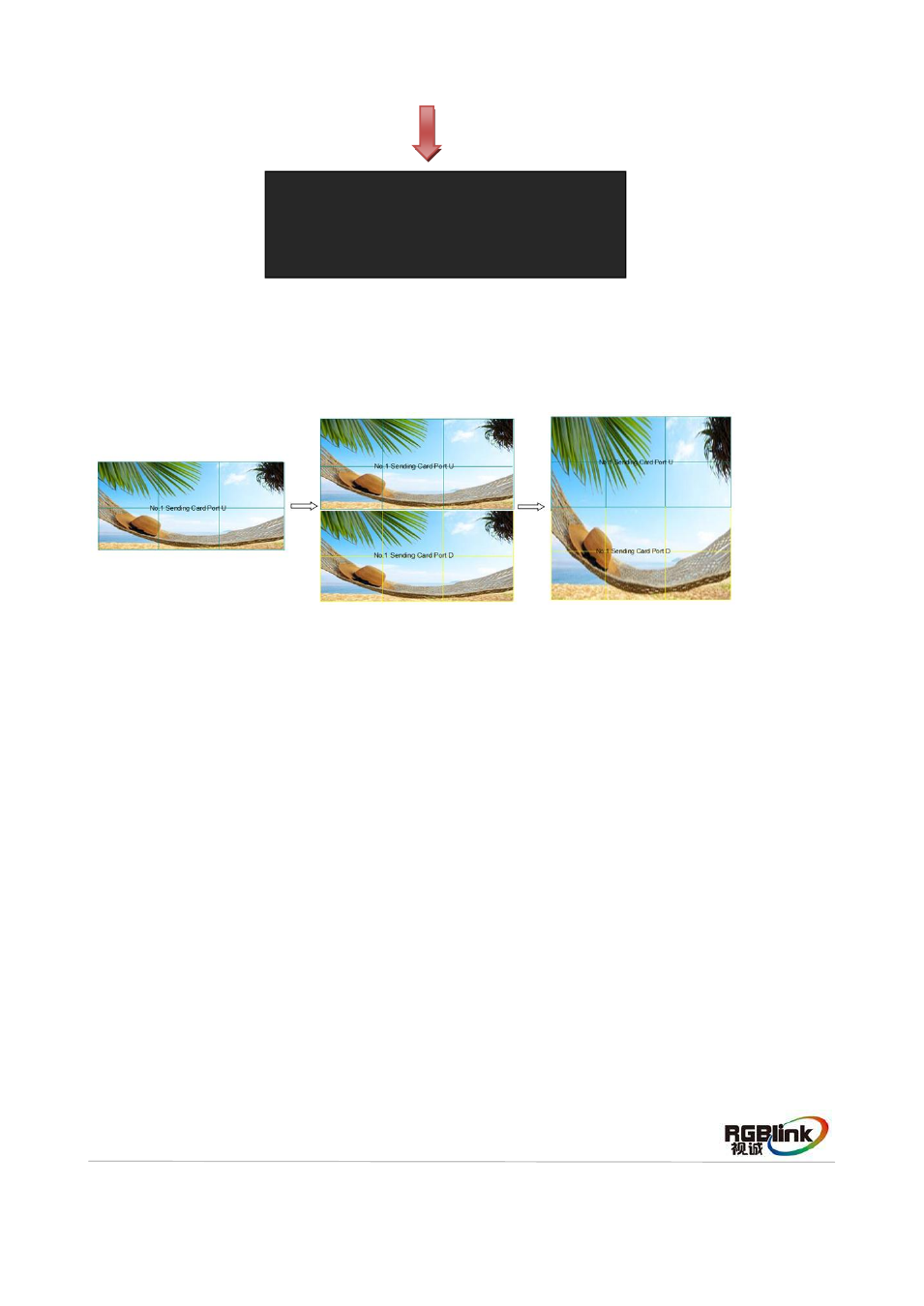
Choose the connection mode, the setting is same as Port U1. Then connection of both the Port D and
Port U of One Sending Card to LED Display is finished.
Rendering is as follows:
3. Connect the Port D and Port U of Two Sending Cards to LED Display
(1) First, make sure the device is in normal operation. The red power indicator lights when
device has power supply and the green signal indicator lights when device has signal
input.
(2) Choose the input signal, for example, choose DVI.
(3) Connect four cables to Port U1, Port D1, Port U2 and Port D2 respectively.
(4) Connect Port D1 and Port U1 of No.1 Sending Card to LED display, the settings are
same as “Connect the Port D and Port U of One Sending Card to LED Display”.
(5) Same as above, connect Port D2 and Port U2 of No.2 Sending Card to LED display.
(6) Turn the knob, choose
knob again, choose
choose NO.2, push the knob to confirm.
>
CONNECTION MODE
SEND TO RECEIVER