Connect the polarotor, Rc2000 back panel – Research Concepts RC2000C User Manual
Page 20
12
RC2000C Az/El Tracking Antenna Controller
Chapter 3
Installation/Setup
Research Concepts, Inc. • 5420 Martindale Road • Shawnee, Kansas • 66218-9680 • USA
www.researchconcepts.com
Connect the Polarotor
tm
as shown in either figure 3.2 or 3.3. Shielded cable is required to minimize
noise pickup.
NOTE: Shielded cable is recommended for the Polarotor
tm
to minimize noise pickup. If a shield
is used it must be connected to J1-9 on the back of the controller and must not be connected at
the antenna.
Azimuth and Elevation Position Sense
If reed switch sensors are used, each axis requires 2 wires in a shielded cable. If Hall effect sensors
are used, each axis requires 3 wires in a shielded cable. Shielded cables are required to minimize noise
pickup that can result in antenna positioning errors. Please refer to figure 3.2 for reed sensor
connections and figure 3.3 for Hall Effect sensor connections.
NOTE: Shielded cables are required for the position sensors. The shields must be connected to
pins J1-4 or J1-6 on the back of the controller and must not be connected at the antenna.
Position count errors due to improper use of the shield on the position sense lines is one of the most
frequent problems encountered during the installation of the RC2000C. Here are the problems that are
encountered:
1. A shielded cable was not used for the position sense wires.
2. The shield is not connected at connector J1 on the rear panel of the RC2000C.
3. The shield is connected to earth ground at the antenna. This results in ground currents flowing in
the shield. The shield must not be connected to anything at the antenna. At the actuator terminal
strip, it is a good idea to place heat shrunk tubing over the frayed fail shielding material, where the
sensor cable insulation is removed.
4. The insulator on the sensor cable is broken and the shield is grounded to something. As in #3, this
results in ground currents.
5. The sensor cable is spliced but the shield has not been spliced, or the shield is spliced but is also
shorted to earth ground. This often occurs when the sensor cables are spliced at a terminal box
near the antenna. The sensor interface cables must be shielded all the way to the actuator.
See the Operation Troubleshooting Tips section of Chapter 7 for more information on count problems.
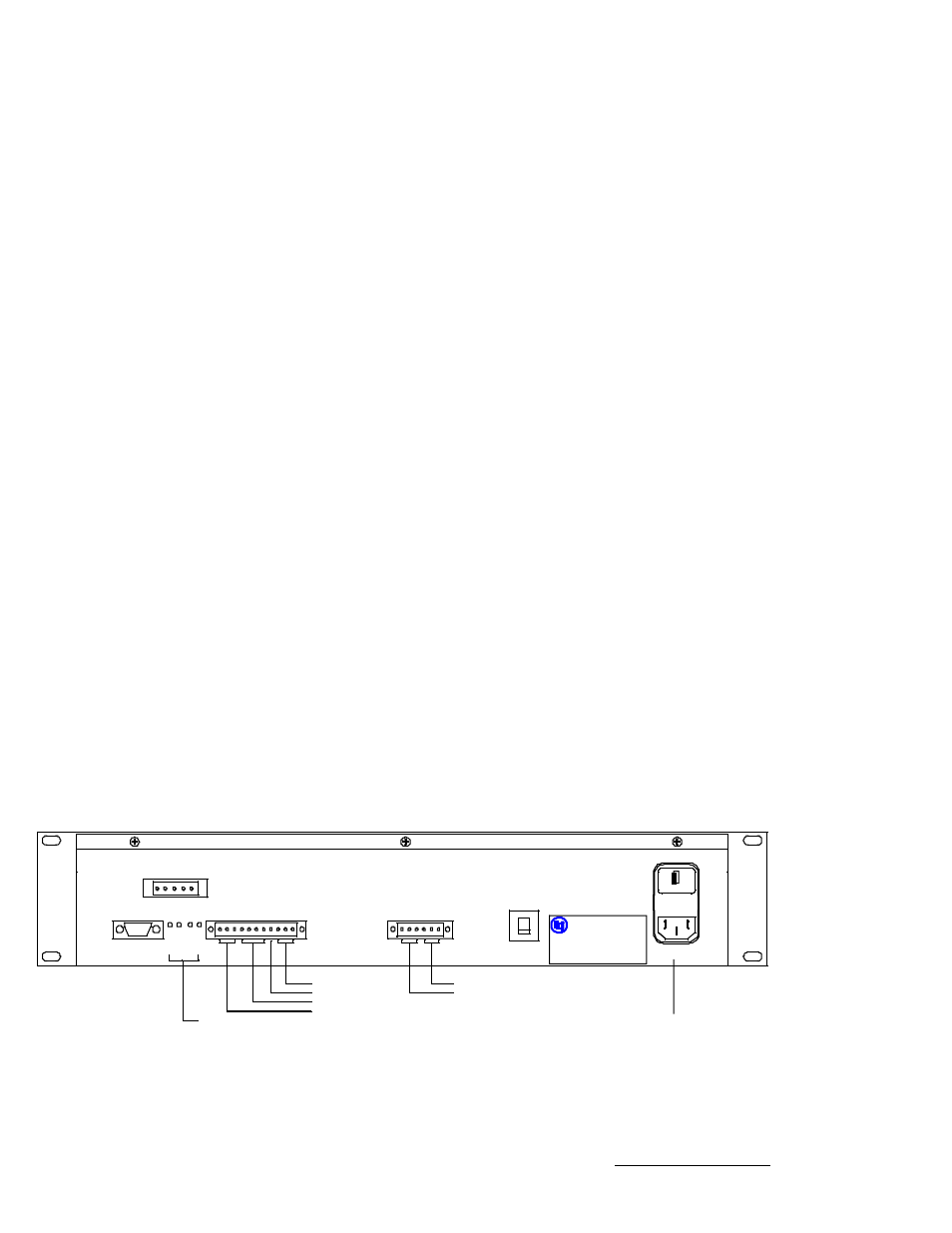
Figure 3.1 - RC2000 Back Panel
J3
1
AGC POTS
COMM
J1
O
F
F
S
E
T
N
I
A
G
G
A
I
N
T
E
S
F
F
O
AGC1
AGC2
1
7
.
5
V
E
S
L
U
P
N
T
R
V
H
+
Z
A
+
L
E
E
L
-
A
Z
-
N
T
R
2
C
G
A
C
G
A
AZ DRIVE (2)
EL DRIVE (2)
SKEW
AUTOPOL INPUT
SENSORS
AGC INPUTS
G
N
D
G
N
D
1
Z
A
1
L
E
E
L
2
A
Z
2
1
J2
A
2
1
BREAKER
DRIVE
RC2000 Back Panel
Research Concepts , Inc .
Shawnee, Kansas
Model: R C2000C
Serial Numbe r: 5420
Date : 09.27.01
EIC Input Power
J4
RTN
REF
SI G
DRIV E
1 2 3 4 5