Unit installation – REMKO PWW Series User Manual
Page 5
5
The following information must be
observed for safe unit installation.
■
The units must be arranged so
that accessed areas and work-
places are not located in the
direct air stream.
■
The units must only be mount-
ed on ceilings or roof construc-
tions with sufficient load bear-
ing capacity.
■
The heat exchangers must be
connected so that no vibrations
can be transferred from the unit
to the pipe system or vice versa.
■
For wall mounting, a minimum
height of 2.5 m to the bottom
edge of the unit must be
maintained.
■
For wall mounting above 4 m,
suction of the recirculated air
should take place from the
ground to ensure uniform
heating.
■
For ceiling mounting below
4 m, the units should be fitted
with an air outlet hood HG 4.
■
For ceiling mounting above
4 m, the units should be fitted
with the ceiling air outlet nozzle
AD.
■
Before connecting the units
to an existing water heating
system, the boiler and pump
must be checked for sufficient
capacity.
■
For maintenance and repair
purposes, a repair switch should
be mounted near to the unit.
■
The gap between the fan
impeller and housing must be
checked for the same distance.
■
Units with fresh air inlet
must be fitted with anti-frost
protection.
Heat exchanger
copper/aluminium
The fin heat exchangers consist
of copper pipes with pressed on
aluminium fins.
The fin assembly is enclosed by a
galvanised steel frame.
Collector, distributor and heating
medium connections are made of
steel.
■
Heating medium connections
are established via threaded
Unit installation
KO
(L 40 x 40 x 3)
e
ø 12.5
d
d
c
a
b
pipe adapters.
■
The water inlet (flow) is
generally
the bottom.
■
The maximum operating tem-
perature is 130°C.
■
The maximum operating pres-
sure is 16 bar.
■
The heat exchangers are not
suitable for operation with
steam or thermal oil.
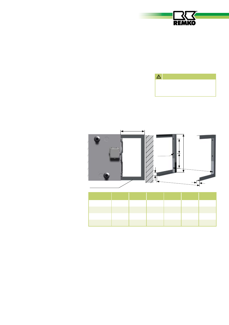
PWW
a
in mm
b
in mm
c
in mm
d
in mm
e
in mm
f
in mm
30
552
432
506
155
270
40
50
632
507
586
192
270
40
80
792
622
746
250
270
40
100
872
732
826
305
340
40
f
f
Bracket KO
for wall and ceiling mounting
Brackets
Brackets (KO) for wall and ceiling mounting (2 per unit) must be inserted
into the recesses in the rear wall of the unit and attached to the unit us-
ing the enclosed screws.
Direct mounting parts such as
mixed-air or filter box must be
attached using a wall fastening
bracket (WFM).
When using local bracket construc-
tions, the minimum wall distance
“e
” must be maintained!
AttENtiON
The brackets must be screwed
to the de-energised unit and
wall or ceiling.