Control unit, 5-stage, Fan motor 400v, two-step – REMKO PWW Series User Manual
Page 19
19
Five-stage control units,
400V/50Hz, three-phase with
indicator light.
Motor protection takes place
by the connection of thermal
contacts.
In the event of a fault, (operati-
on of the thermal contacts), the
internal contactor drops out and
disconnects the motor from the
power supply.
After the motor has cooled down
and the fault cleared, the mode se-
lector switch must first be switched
to the “0“ position and then back
to the required operating position
(speed position).
The control units have a connec-
tion for external control devices,
e.g. room thermostat, anti-frost
thermostat, servomotor, recirculat-
ing pump, indicator light, solenoid
valve, mixer, etc. (observe contact
rating).
Control unit, 5-stage
Voltage
Current
Degree of
protection
Weight
Control unit
V
A
IP
kg
3 EG
400
3.0
54
11.1
5 EG
400
5.2
54
15.6
EG
TK
TK W2 U2 V2
W1
V1
U1
J
N L1 L2 L3
U1 V1 W1
TK TK
RT RT
N L1 L2 L3
PE
J
FS FS
12 11 14
N L L
Raum-
thermostat
Frostschutz-
thermostat
250VAC
max.2A
230VAC
max.1A
Eingangsspannung
400V / 3~N / 50 Hz
3~ Motor mit
Thermokontakten
Kontaktbelastung
Lüfter
Aus/Ein
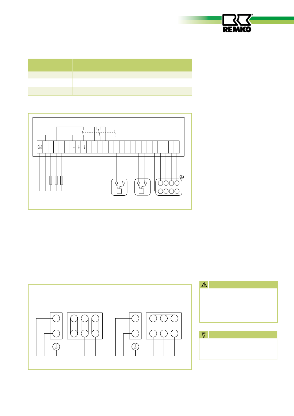
Wiring diagram five-stage control unit 3 EG/5 EG
hohe Drehzahl
∆
- Schaltung
niedere Drehzahl
Y
- Schaltung
TK
W2 U2 V2
TK
U1
V1 W1
PE
L1
L2
L3
TK
W2 U2 V2
TK
U1
V1 W1
PE
L1
L2
L3
Fan motor 400V, two-step
D / Y switching and thermal contacts
Standard units
We reserve the right to make changes to dimensions and design in the interest of technical advances.
Wiring diagram
NOtE
All electrical wiring terminals
must be checked for tightness
and retightened if necessary.
AttENtiON
Electrical heater connection
must be carried out by au-
thorised specialists as defined
in DIN EN 60335-1 and VDE
0116.