Remko pww, Switchgear sw 2 - 380 di – REMKO PWW Series User Manual
Page 16
16
REMKO PWW
control unit.
The thermal contacts of all motors
must be connected in series.
Note on safe operation
Earthing, multiple earthing or
protection switching and mains
protection must be carried
out on-site according to VDE
specifications and the regulations
of the responsible electricity supply
company. Only specialists may
establish electrical connections
based on the wiring diagrams in
compliance with the applicable
regulations, taking into account
local regulations.
three-phase 400V,
two-speed fan
maximum switching capacity
4 kW,
surface mounting, motor
protection by means of built-in
thermal contacts in fan motor.
Design
Sturdy plastic housing,
Degree of protection IP 54.
Totally-insulated according to VDE.
Front plate with symbols for switch
positions, supply and protective
conductor terminals, main con-
tactor, control switch with the
functions “Off/Setting 1/Setting
2“, control fuse, indicator light
(extinguishes on fan faults and/or
interruption of power supply
to
control unit), fault reset button,
terminals for motor output, termi-
nals for thermal contacts and room
thermostat.
Reconnection after a fault
After each main break or fan fault,
the “Fan fault reset button“ must
be pressed once!
Multiple series connection
The control unit is suitable for
multiple series connection. Several
motors in the same circuit can be
connected to a control unit
The total rating of the connected
motors must not exceed the per-
missible switching capacity of the
Switchgear SW 2 - 380 Di
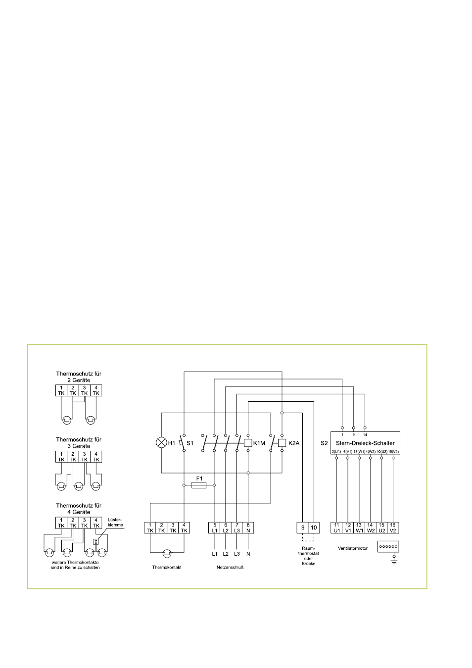
Circuit and wiring diagram
We reserve the right to make changes to dimensions and design in the interest of technical advances.
S1 = Fan fault reset button
K2A
= Auxiliary relay
K1M
= Contactor for fan motor
H1 =
Indicator light
F1 =
Control fuse
S2 =
Control switch