Electrical wiring diagram clk 80-rv – REMKO CLK 80-RV User Manual
Page 18
18
REMKO CLK 80/170-RV
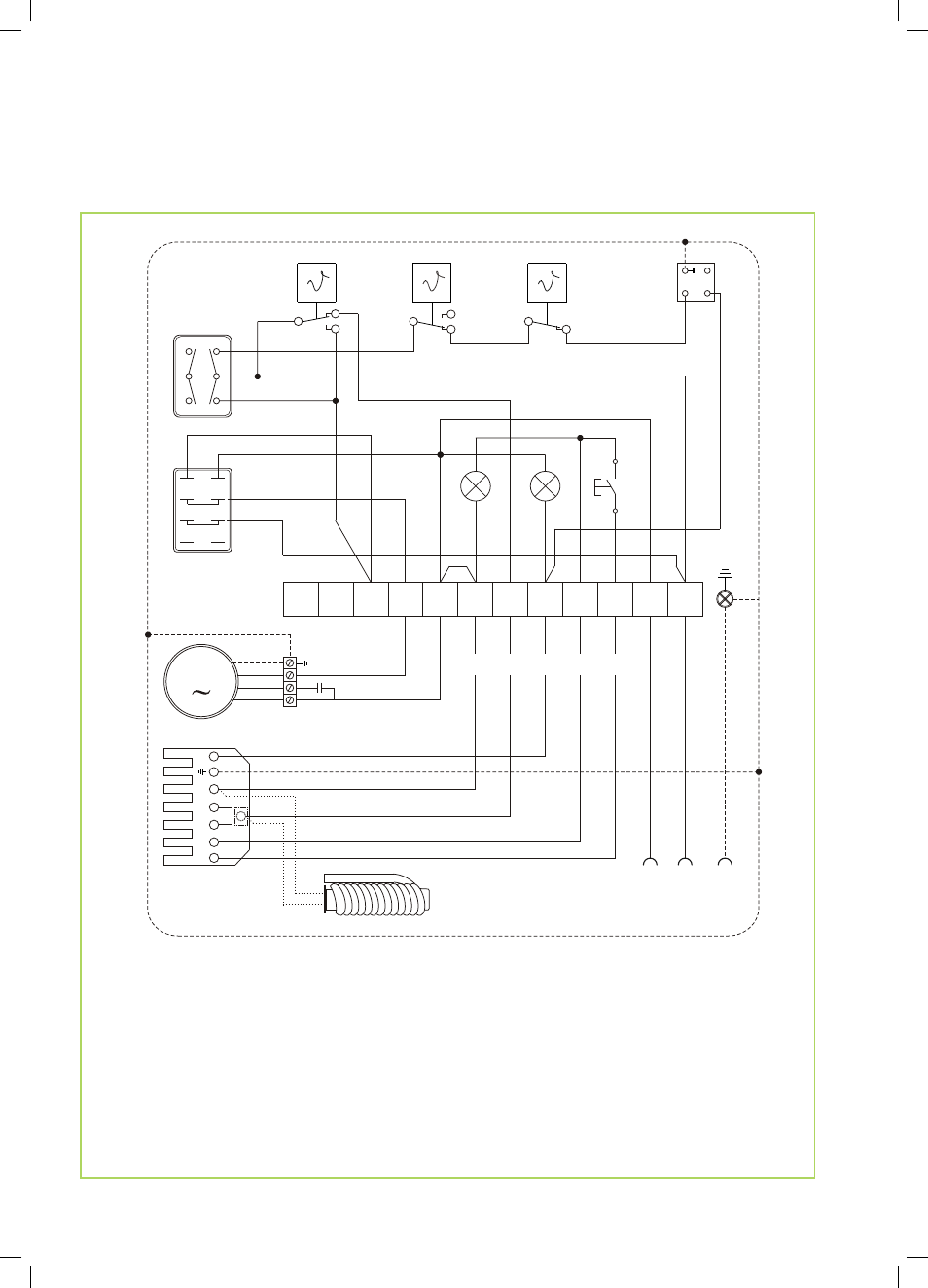
Electrical wiring diagram CLK 80-RV
We reserve the right to modify the dimensions and design as part of the ongoing technical development process.
TW
RT
TR
STB
S1
WS
1A
2A
3A
4B
5B
6B
H2
H1
KL
1
2
3
4
5
6
7
8
9
L1
N
T1
T2
S
3
B
4
I
II
10
11
12
2
1
3
S2
M
HR
N
blau
schwarz
1
1
1
2
2
2
4
4
#2
#4
#3
#1
HW 07.13
N
PE
L1
N
230 V / 50 Hz
C
#5
ÖV
Option (EDV-Nr.: 1071411)
A
B
11
14
31
34
12
32
Legend:
C = Capacitor
H1 = Operating lamp (green)
H2 = External burner fault lamp (red)
HR = Auxiliary relay
KL = Terminal block
M = B3 Fan motor
ÖV = Multiflex oil pre-heating (option)
RT = Thermostat receptacle
S1 = Operating switch
S2 = Reset button - burner relay
STB = Safety temperature limiter
TR = Temperature controller
TW = Temperature monitoring device
WS = Burner connector, 7-pole
(only fitted with factory burner delivery)