Feature descriptions (con.), Voltage margining – Delta Electronics DNT04 User Manual
Page 9
DS_DNT04SIP3A_09262007
9
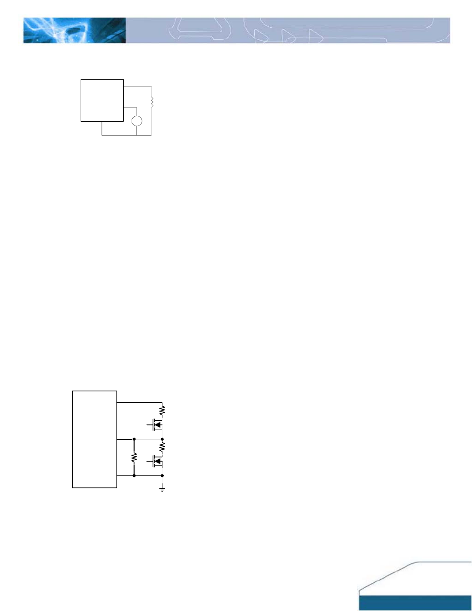
Figure 30: Circuit configuration for output voltage margining
Vo
On/Off
Vin
GND
Trim
Q2
Q1
Rmargin-up
Rmargin-down
Rtrim
Vo
TRIM
GND
RLoad
Vtrim
+
_
Figure 29:
Circuit Configuration for programming output voltage
using external voltage source
The amount of power delivered by the module is the
voltage at the output terminals multiplied by the output
current. When using the trim feature, the output voltage of
the module can be increased, which at the same output
current would increase the power output of the module.
Care should be taken to ensure that the maximum output
power of the module must not exceed the maximum rated
power (
Vo.set x Io.max ≤ P max)
.
Voltage Margining
Output voltage margining can be implemented in the DNT
modules by connecting a resistor, R
margin-up
, from the Trim
pin to the ground pin for margining-up the output voltage
and by connecting a resistor, R
margin-down
, from the Trim pin
to the output pin for margining-down. Figure 30 shows the
circuit configuration for output voltage margining.
If
unused, leave the trim pin unconnected.
A calculation tool
is available from the evaluation procedure which
computes the values of R
margin-up
and R
margin-down
for a
specific output voltage and margin percentage.
FEATURE DESCRIPTIONS (CON.)