Features descriptions (con.), Features descriptions – Delta Electronics DNT04 User Manual
Page 8
DS_DNT04SIP3A_09262007
8
FEATURES DESCRIPTIONS
(CON.)
Over-Temperature Protection
The over-temperature protection consists of circuitry that
provides protection from thermal damage. If the
temperature exceeds the over-temperature threshold
the module will shut down. The module will try to restart
after shutdown. If the over-temperature condition still
exists during restart, the module will shut down again.
This restart trial will continue until the temperature is
within specification.
Output Voltage Programming
The output voltage of the DNT can be programmed to any
voltage between 0.75Vdc and 3.3Vdc by connecting one
resistor (shown as Rtrim in Figure 28) between the TRIM
and GND pins of the module. Without this external
resistor, the output voltage of the module is 0.7525 Vdc.
To calculate the value of the resistor Rtrim for a particular
output voltage Vo, please use the following equation:
Ω
⎥⎦
⎤
⎢⎣
⎡
−
−
=
5110
7525
.
0
21070
Vo
Rtrim
For example, to program the output voltage of the DNS
module to 1.8Vdc, Rtrim is calculated as follows:
Ω
=
Ω
⎥⎦
⎤
⎢⎣
⎡
−
−
=
K
Rtrim
15
5110
7525
.
0
8
.
1
21070
DNT can also be programmed by apply a voltage
between the TRIM and GND pins (Figure 29). The
following equation can be used to determine the value of
Vtrim needed for a desired output voltage Vo:
(
)
7525
.
0
1698
.
0
7
.
0
−
×
−
=
Vo
Vtrim
For example, to program the output voltage of a DNT
module to 3.3 Vdc, Vtrim is calculated as follows
(
)
V
Vtrim
267
.
0
7525
.
0
3
.
3
1698
.
0
7
.
0
=
−
×
−
=
Vo
TRIM
GND
RLoad
Rtrim
Figure28:
Circuit configuration for programming output voltage
using an external resistor
FEATURES DESCRIPTIONS
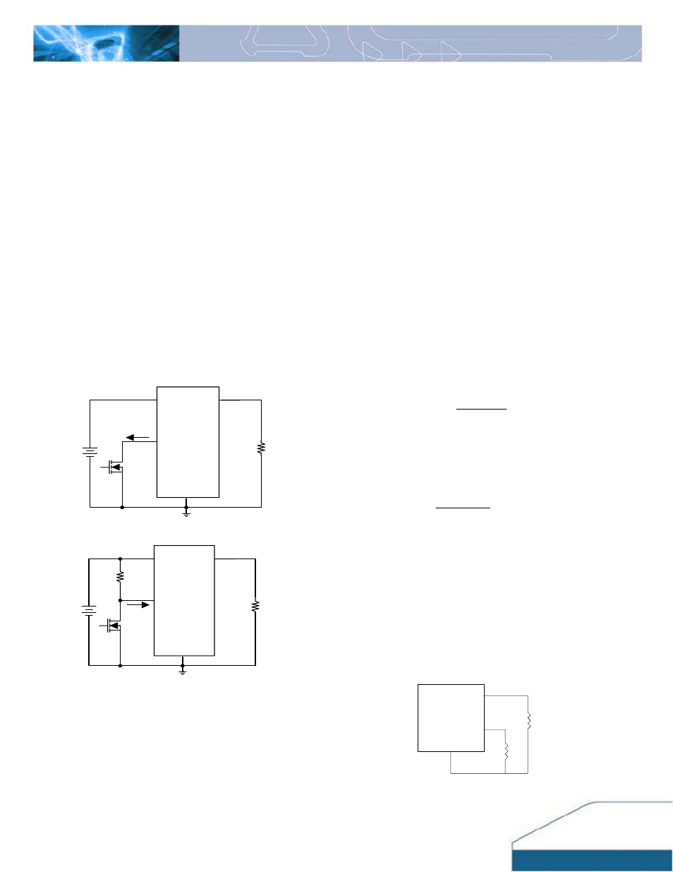
Remote On/Off
The DNT series power modules have an On/Off pin for
remote On/Off operation. Both positive and negative
On/Off logic options are available in the DNT series
power modules.
For positive logic module, connect an open collector
(NPN) transistor or open drain (N channel) MOSFET
between the On/Off pin and the GND pin (see figure 26).
Positive logic On/Off signal turns the module ON during
the logic high and turns the module OFF during the logic
low. When the positive On/Off function is not used, leave
the pin floating or tie to Vin (module will be On).
For negative logic module, the On/Off pin is pulled high
with an external pull-up resistor (see figure 27). Negative
logic On/Off signal turns the module OFF during logic
high and turns the module ON during logic low. If the
negative On/Off function is not used, leave the pin
floating or tie to GND. (module will be On)
Vo
On/Off
Vin
GND
Q1
RL
I
ON/OFF
Figure 26: Positive remote On/Off implementation
Vo
On/Off
Vin
GND
Q1
RL
Rpull-
up
I
ON/OFF
Figure 27: Negative remote On/Off implementation
Over-Current Protection
To provide protection in an output over load fault
condition, the unit is equipped with internal over-current
protection. When the over-current protection is
triggered, the unit enters hiccup mode.
The units operate
normally once the fault condition is removed.