Base mount upgrade kit, Rear top mount upgrade kit – Posiflex JIVA KS-7717 User Manual
Page 11
Part 11
as arrowed in the same picture. Gently arrange the excessive length of this
cable back in the hole and screw-fit it back to the position originally occupied
by the cover. Please reserve the cover if there is chance to have the side mount
kit removed in the future.
BASE MOUNT UPGRADE KIT
Before installing base mount upgrade kit, be sure to remove Posiflex logo for
screw hole view. Please follow the instructions on the manual that comes along
with the customer display PD- 306/U, 309, 310/A, 2602/U, 2604/A, 76x2,
76x4, and LM-6101B, LM-6501B, LM-80X5 if installed.
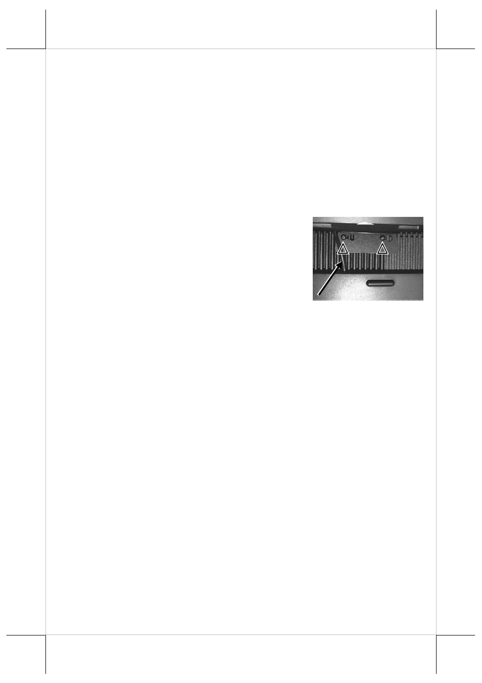
REAR TOP MOUNT UPGRADE KIT
1.
For Customer Pole Display:
Please apply carefully the 2 small fixation shoulder
screws that come along with the rear top mount
upgrade kit to the back of the terminal at the screw
holes triangle marked in the 2 upper right pictures.
However please do not screw them to the bottom but
at a position that is about 1 turn loose from the
bottom. Similarly please loosen the screws by 1 turn for some KS models with
these 2 screws preinstalled. Hook the rear bracket of the upgrade kit onto the
shoulder screws with the large circular holes. Slide to the right of the upgrade
kit and gently tighten the shoulder screws. Do not overdo the tightening or
unrecoverable thread damage will occur. Arrange the interface cable to
enter the base stand at a notch on the edge near the lock/release button as
indicated by white arrow in the above picture. Remember to enable the +5 V
DC supply in the COM port of the main unit for the upgrade kit if the serial
interface model is used. The power supply in the I/O port must be disabled if it
is no longer to support these intended devices otherwise any damage or loss
caused consequently shall be out of product warranty!
2.
To Install Second LCD Display LM-8035
1. Remove the logo label on the top of the back side of main unit.
2. Secure the metal bracket shipped with LM-8035 with four screws onto
the main unit.
3. Align the screw holes of the metal bracket on LM-8035 with those on the
bracket just attached to the main unit.
4. Secure the three screws to attach LM-8035 to the terminal.