Two condenser head pressure module, Installation & wiring, Technical guide 4 – Orion System Two Condenser Head Pressure Module User Manual
Page 4: Power supply, Environmental requirements, Mounting
Two Condenser Head Pressure Module
Technical Guide
4
Installation & Wiring
Power Supply
The Two Condenser Head Pressure Module requires a 24 VAC power
connection with an appropriate VA rating.
If you will be connecting the Two Condenser Head Pressure Module to
any of the VCM-X series controllers, one of the most important checks
to make before powering up the system for the fi rst time is to make sure
that the controller is confi gured properly for your application. Refer to
the VCM-X Controller Technical Guide or VCM-X Modular E-BUS
Controller Technical Guide for more information.
WARNING: Observe polarity! All boards must be wired
GND-to-GND and 24 VAC-to-VAC. Failure to
observe polarity could result in damage to the
boards.
Environmental Requirements
The Two Condenser Head Pressure Module needs to be installed in an
environment that can maintain a temperature range between -30°F and
150°F and not exceed 90% RH levels (non-condensing).
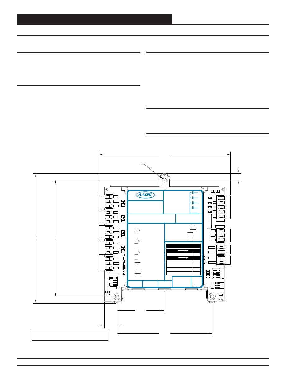
Mounting
The Two Condenser Head Pressure Module is housed in a plastic en-
closure. It is designed to be mounted by using the 3 mounting holes in
the enclosure base. It is important to mount the module in a location
that is free from extreme high or low temperatures, moisture, dust, and
dirt. Be careful not to damage the electronic components when mount-
ing the module.
See Figure 2 for Module dimensions (in inches).
5.04
5.64
5.71
2.07
0.55
4.14
0.29
0.18 DIA. TYP.
1003
1002
10uF
300
1
2
4
8
SERIA
L
#
C2
D3
D4
R7
R9
R11
R12
R13
R14
R23
R24
R25
R26
R28
R29
R30
SW1
D12
D13
R53
R54
TB3
C20
R34
R
50
SW2
+5V
SIG 2
GND
1003
1002
10uF
1003
1002
10uF
1003
1002
10uF
4751
4751
4751
4751
OFF
OFF
OP
T
ION
S
ALARM
ANALOG
STAT
+5V
COMM
GND
SIG 4
300
GND
BIN 2
R1
4
R2
4
GND
1002
1002
1002
1002
1002
1002
1002
1002
RELAYS
ADDRESS
SIG 3
+5V
GND
BIN 1
COM
+5V
SIG 1
R3
R4
Rc
AO1
AO2
PWM1-
PWM1+
PWM2-
PWM2+
.01uF
PWR
Note: Height is 1.49 inches.
LED BLINK CODES
LED NAME
STAT
BLINKS QTY. OF SENSORS INSTALLED
LED NAME
ALARM
NO PROBLEMS
0
NO SENSORS DETECTED
1
HIGH HEAD PRESSURE DETECTED
2
LOW HEAD PRESSURE DETECTED
3
WattMaster Label
Rev.: 1H
#LB102081
E-BUS
Connector
E-BUS
Connector
+5V
SIG 1
GND
+5V
SIG 2
GND
+5V
SIG 3
GND
+5V
SIG 4
GND
+24
VAC
GND
BIN 1
BIN 2
COM
HEAD
PRESSURE
TRANSDUCER #1
HEAD
PRESSURE
TRANSDUCER #2
HEAD
PRESSURE
TRANSDUCER #3
HEAD
PRESSURE
TRANSDUCER #4
COMMON
PWM2+
Two Condenser Head Pressure Module
2C
Orion No.:OE370-23-HP
AAON Coil No.:
30310
Circuit A1
Circuit A2
Circuit B1
Circuit B2
www.aaon.com
AO1
AO2
GND
COND. A & B ENABLE
COOL ENABLE
RELA
Y
C
ONT
A
CT
RA
TING
IS
1
A
MP
MAX
@
24
V
A
C
COND. A ENABLE
COND. B ENABLE
COND. A SIGNAL
COND. B SIGNAL
COOL ENABLE
COOL ENABLE
PWM1-
PWM1+
PWM2-
COND. FAN A
COND. FAN B
COND. FAN A
COND. FAN B
GND
R1
R2
R3
R4
RC
RELAY COMMON
Figure 2: Two Condenser Head Pressure Module Dimensions