Operator interfaces technical guide 7, Service tool and system manager, Modular system manager – Orion System VCM User Manual
Page 7
Operator Interfaces
Technical Guide
7
Mode Selection Buttons
Button
Description
Modular Service Tool
System Manager
STATUS
Pressing this button
takes you directly to
the controller
“Status” screens
Pressing this button
takes you directly to
the controller
“Status” screens
SETPOINTS
Pressing this button
takes you directly to
the controller
“Setpoints” screens
Pressing this button
takes you directly to
the controller
“Setpoints” and
“Configuration”
Menu
SCHEDULES
Pressing this button
takes you directly to
the controller
“Schedules” screens
Pressing this button
takes you directly to
the controller
“Schedules” screens
OVERRIDES
Pressing this button
takes you directly to
the controller
“Overrides” screen.
See the “Override
Button” section of
this manual for a
description of this
function.
See Note 1 below.
Pressing this button
takes you directly to
the controller
“Overrides” screen.
See the “Override
Button” section of
this manualfor a
description of this
function.
See Notes 1 & 2
below.
ALARMS
Pressing this button
takes you directly to
the controller
“Alarms” screen.
See the “Alarms
Button” section of
this manual for a
description of this
function.
See Note 1 below.
Pressing this button
takes you directly to
the controller
“Alarms” screen.
See the “Alarms
Button” section of
this manual for a
description of this
function.
See Notes 1 & 2
below.
CONFIGURATION
Pressing this button
takes you directly to
the controller
“Configuration”
screens
Not Available
Use “Setpoints”
Button To Access
Menu
BALANCE-TEST
Pressing this button
takes you directly to
the controller
“Balance-Test”
screens
Not Available
Notes:
1.) This button only functions when the system is configured
for “Network Mode” or “Multiple MGRS Mode”. It will not
function in ‘Stand Alone Mode”.
2.) The “Search For Units” function must be performed on the
System Manager upon initial system setup before this function
will be available. See the “System Manager NM & MM Loop
Search” section of this manual for complete instructions on
performing a loop search.
Service Tool And System Manager
Entering Unit ID (Address)
With both the Modular Service Tool and the Modular System Manager
You must enter the ID (Address) of the controller you wish to program
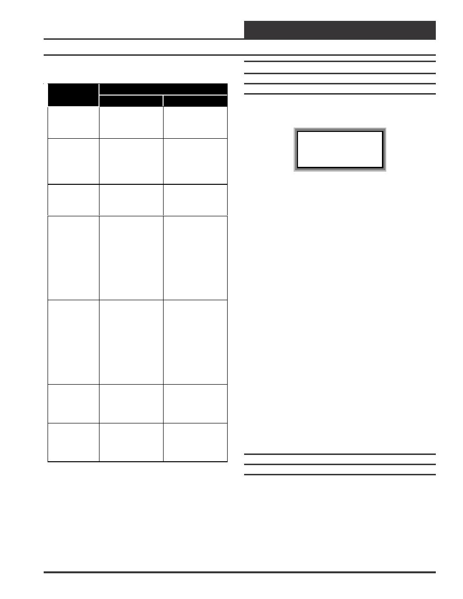
Unit Selection
Enter Unit ID#
Selected ID#: xxxx
With the main menu screen displayed, press the function key associated
with the operation (setpoints, configuration, etc.) you want to perform.
The screen shown above will appear asking you to enter a unit I.D.#
(controller address). Put in the ID# of the controller you wish to com-
municate with then press the “Enter” key.
If this is Network System (the system has a CommLink), the Unit ID is
actually two separate numbers, combined into one value. The first part
of the number contains the Loop Address at which the controller is
located. The second part of the number contains the actual controller
address. See Examples #1 & #2 below.
If this is a Stand Alone System (system without a CommLink) this will
be a number between 1 and 59. It is recommended the address be set to
1. See example #3 below.
EXAMPLE #1
You would like to view the 3rd controller on the 5th loop. Enter “503”
as the Unit ID.
EXAMPLE #2
You would like to view the 12th controller on the 24th loop. Enter “2412”
as the Unit ID
EXAMPLE #3
You would like to view the only controller on the loop. Enter 1 as the
Unit ID. No loop number is required since there is only one loop.
Hit the “Enter” key after entering the unit ID. If you are using the Modular
Service Tool you will be taken directly to the first screen for the opera-
tion you are trying to program.
Modular System Manager
System Manager Initialization Screens
When the System Manager is powered up, the first screen displays the
current version of the software installed in your System Manager and
whether your system is configured for Network or Stand-Alone opera-
tion. If it is configured for Stand-Alone operation, only the HVAC unit
controller that the System Manger is connected to is available for pro-
gramming. On a Networked System, all controllers on the communica-
tions loop are available for programming by entering their loop address
(ID). If an Interconnected System is connected to the System Manager
all controllers that are connected to the communication loop are avail-
able for programming.