Operator interfaces technical guide 47, Damper force modes – Orion System VCM User Manual
Page 47
Operator Interfaces
Technical Guide
47
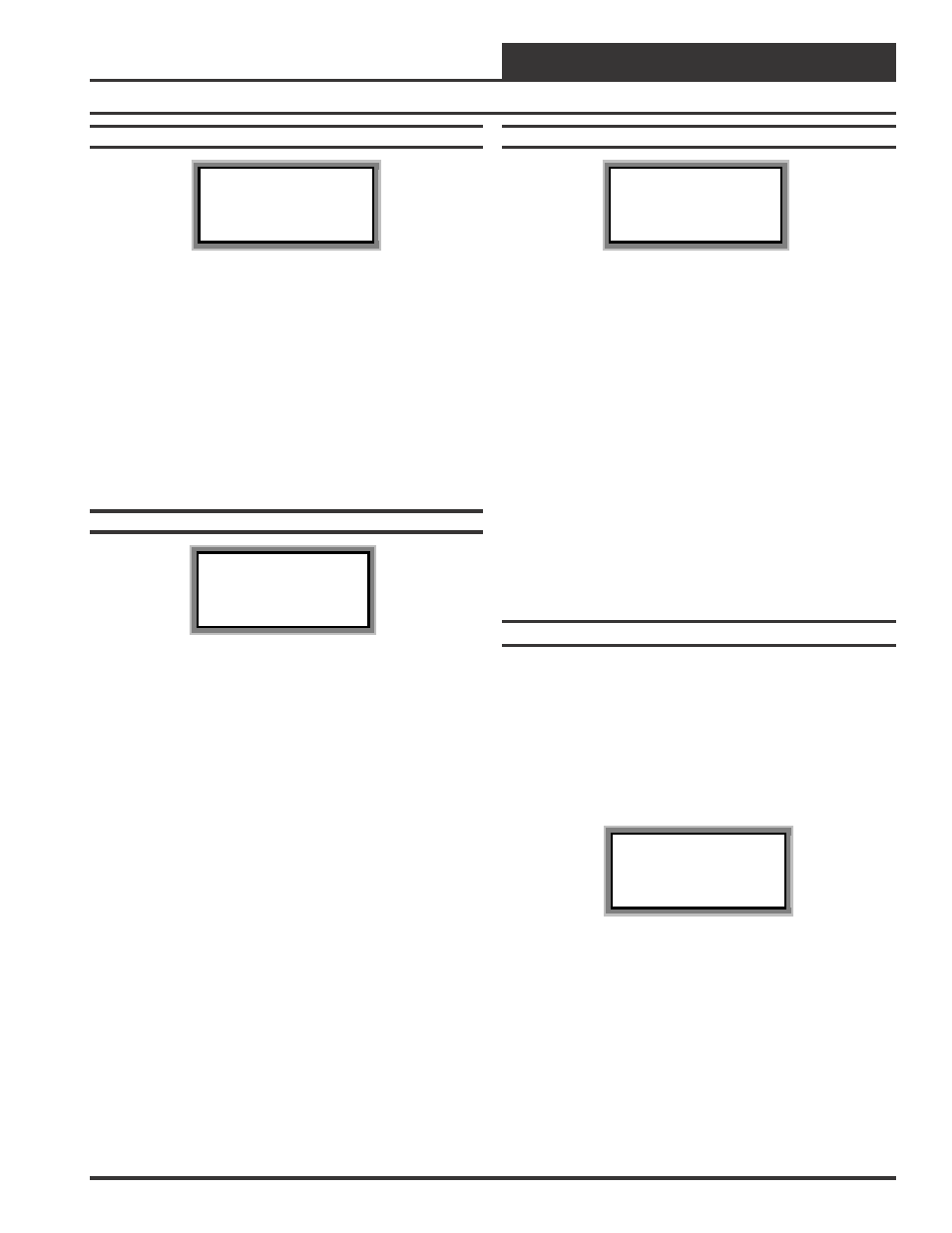
Status Screen #5
HC Box v1.04 IDxxxx
Damper FRC: xxx %
Airflow : xxxx CFM
Desired : xxxx CFM
Line 2
Current Zone Damper Position If the user has entered
a FORCE command, the letters FRC will appear. If
this is normal damper operation, the FRC is not
displayed.
Line 3
If this is a Pressure Independent box, the current
Airflow will be displayed. If not, this line will display
the desired damper position.
Line 4
If this is a Pressure Independent box, this line will
display the Desired CFM the box would like to
provide to the zone. If not, this line will display
[Controls to +/- 3%] to indicate how accurately the
damper will maintain the desired position.
Status Screen #6
HC Box v1.04 IDxxxx
Fan Status : OFF
Heating Relay#1: OFF
Heating Relay#2: OFF
Line 2
If this is a Fan Powered box, this line will display the
Fan On/Off Status. On non fan powered boxes, this
line will display: Exp Relay 1 Not Used
Line 3
If your VAV Box Controller has been configured to
control reheat stages, this line reflects the On/Off
Status of the first stage of Reheat. If proportional
heating is used this line will display “Heating
Signal: xxx %”. If you have 3 stages of reheat this
line will display the total number of active heating
stages.
Example:
“1 Reheat Stages On” or
“2 Reheat Stages On” or
“3 Reheat Stages On”
Line 4
If your VAV Box Controller has been configured to
control reheat stages, this line reflects the On/Off
Status of the second stage of Reheat. If you have 3
stages of reheat as explained on line 2, this line will be
blank.
Status Screen #7
HC Box v1.04 IDxxxx
NO ALARMS!
Line 2
Blank
Line 3
NO ALARMS!
This is displayed if no alarms are detected. If there are
one or more alarms active, the possible messages are
shown below:
SPACE SENSOR FAILURE
CFM SENSOR FAILURE
DAMPER OPENING ALARM
DAMPER CLOSING ALARM
HI SPACE TEMP ALARM
LO SPACE TEMP ALARM
DPR FEEDBACK FAILURE
Line 4
Blank
Damper Force Modes
Damper Force Modes are available for testing or balancing the system.
These Force Modes can be accessed and programmed from either the
System Manager or the Modular Service Tool.
System Manager Instructions
To access the Damper Force Modes from the System Manager, press
the “Setpoints” key. You will then see the unit ID screen. Enter the unit
ID of the controller you wish to access and press "Enter". The follow-
ing screen will appear.
1)Change Setpoint
2)Configure Unit
3)Damper Force
ESC) Exit Menu
Press “3” on the keypad and then the "Enter" key. You will then see the
unit ID screen. Enter the unit ID of the controller you wish to access
and press "Enter". At this time the password screen will be displayed.
Enter your level 2 password. Press "Enter" and the damper force modes
screen will be displayed.