Programming the vcm controller, Technical guide operator interfaces 20 – Orion System VCM User Manual
Page 20
Technical Guide
Operator Interfaces
20
Programming The VCM Controller
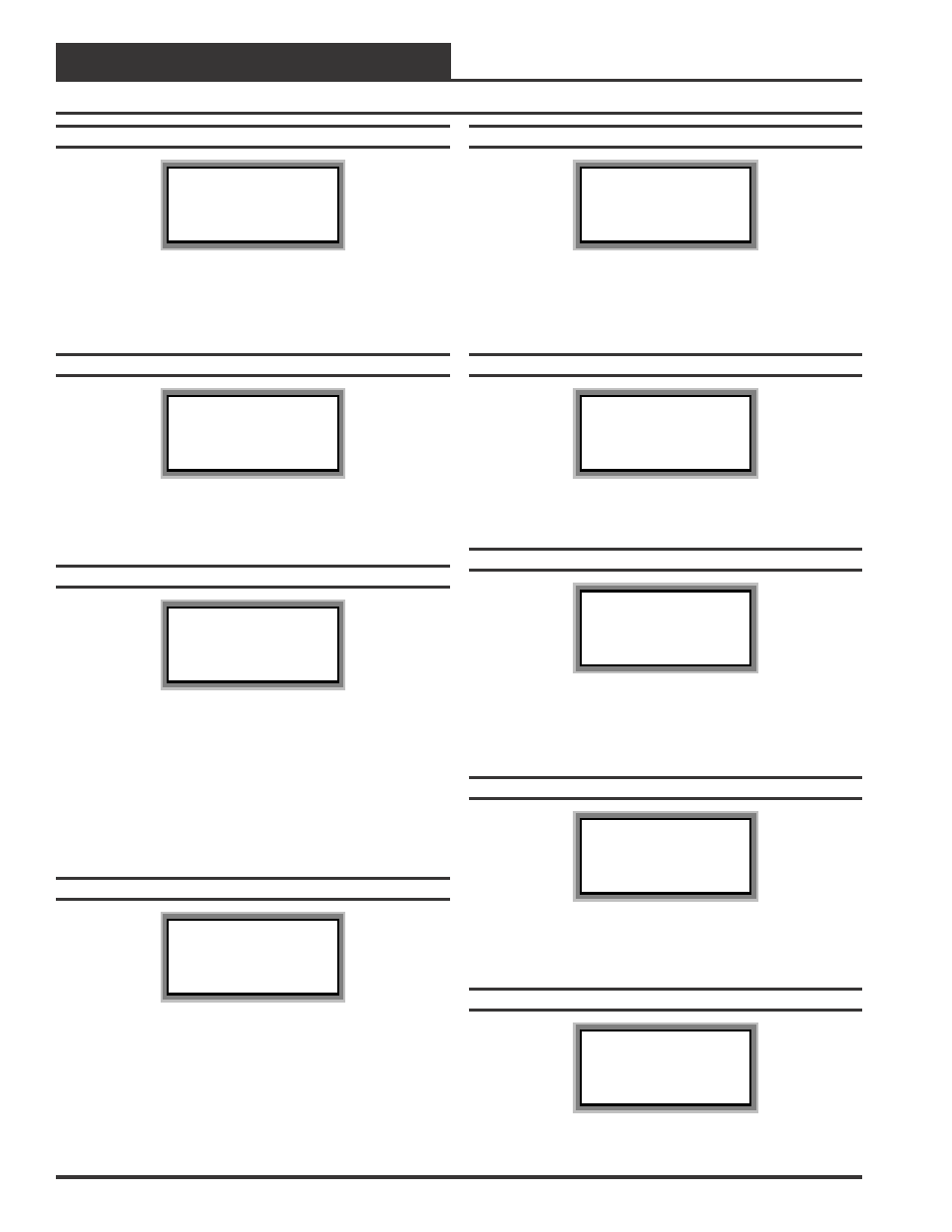
Configuration Screen #22
VCM Cnfg ID 59
CO2 Sensor
Output Signal: 0
[0=None 1=mA 2=VDC]
The VCM needs to know what type of CO
2
sensor signal output is be-
ing provided. Enter a “2” for a 0-10 VDC CO
2
sensor signal (standard
sensor used). Enter a “1” for a 4-20 mA CO
2
sensor signal. Enter a ”0”
if no CO
2
sensor is used
Configuration Screen #23
VCM Cnfg ID 59
CO2 Sensor Maximum
Scale: 2000 PPM
Enter 0 If No Sensor
The VCM needs to know the CO
2
Sensor scaling for proper reading of
the CO
2
Sensor output. The Standard CO
2
Sensor should be scaled to
2000 PPM.
Configuration Screen #24
VCM Cnfg ID 59
Building Pressure
Mod Control: NO
[0=NO 1=YES]
Enter a “1” for “YES” if Modulating Building Pressure Control is needed.
Modulating Building Pressure Control is used for a VFD Exhaust Fan
or a Modulating Exhaust Fan Damper Actuator for Direct Acting Build-
ing Pressure Control. Modulating Building Pressure Control is also used
for a modulating outdoor air damper actuator for Reverse Acting Build-
ing Pressure Control. Enter a “0” for “NO” if Modulating Building Pres-
sure Control is not needed when using a Constant Volume Exhaust Fan
for On/Off Control.
Configuration Screen #25
VCM Cnfg ID 59
Building Pressure
Rev Acting: NO
[0=NO 1=YES]
Enter a “1” for “YES” if Reverse Acting Building Pressure control is
needed. Reverse Acting Building Pressure Control can either be On/
Off or Modulating Control. Modulating Control is normally used for
this configuration. On a drop in Building Pressure, below the Building
Static Pressure Setpoint, the Outdoor Air Damper will modulate open
to increase pressure.
Configuration Screen #26
VCM Cnfg ID 59
Building Pressure
Output Signal: 0
[0=0-10V 1=2-10V]
This Screen is used to configure the Building Pressure Output Signal
voltage needed for your application. You can select either a 0-10 VDC
signal (default) or enter a “1” to make the output signal 2-10 VDC as
required by the device you are using to control the pressure.
Configuration Screen #27
VCM Cnfg ID 59
Air To Air Heat Pump
Control: NO
[0=NO 1=YES]
Enter a “1” for “YES” if the HVAC unit is an Air to Air Heat Pump.
Configuration Screen #28
VCM Cnfg ID 59
Rev. Valve Active
During: Cool
[0=Heat 1=Cool]
Enter a “0” for “Heat” if your Air to Air Heat Pump unit activates its
Reversing Valve during Heating operation. Enter a “1” for “Cool” if
your Air to Air Heat Pump unit activates its Reversing Valve during
Cooling operation.
Configuration Screen #29
VCM Cnfg ID 59
Smoke Detector
Input: NO
[0=NO 1=YES]
The VCM needs to know if a Smoke Detector is connected to its binary
input. If the Smoke Detector input is active, the Supply Fan, Heating
and Cooling Relay Outputs will be disabled.
Configuration Screen #30
VCM Cnfg ID 59
Return Air Bypass
Control: NO
[0=NO 1=YES]
Enter a “1” for “YES” if your HVAC unit requires Return Air Bypass
Control.