Orion System VCM User Manual
Page 5
Operator Interfaces
Technical Guide
5
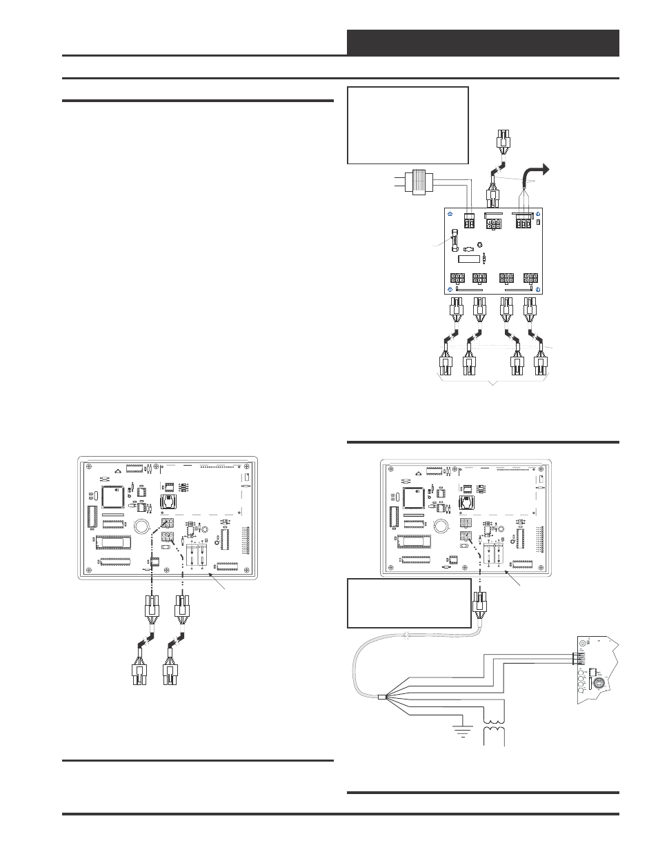
Modular System Manager
As previously described, when you are connecting the Modular Sys-
tem Manager to a Networked System, the Modular System Manager is
connected to the communications and power loop of the system via
modular cables. These cables simply plug into the System Manager
board and to any device with modular connectors on any local loop on
the system. Devices with modular connectors include the Power/Comm
Distribution Board, VAV/Zone controller and the MiniLink Polling De-
vice. By using these plug in connections wiring errors are virtually elimi-
nated and system installation is fast and easy. See Figure 4 for typical
connection information. See Figure 5 for typical Power/Comm board
wiring and connection information.
When the System Manager is to be connected to a Stand Alone system,
a 12 ft. cable with modular connectors on one end and stripped wire
ends on the other end is provided for this purpose. This is used to facili-
tate connecting communications and power wiring to the Modular Sys-
tem Manager from a 24 VAC power source and to the HVAC unit con-
troller communication wiring terminals. See Figure 6 for wiring de-
tails. If the supplied cable wire is not long enough for your installation,
a standard modular cable of the correct length can be purchased through
WattMaster and one of the modular connectors can be cutoff to allow
for the transformer and communication terminal wiring connections. It
is recommended that you do not splice the communications wire if at all
possible. The transformer should be rated at 6 VA minimum power out-
put.
All Modular Power/Comm
Cables Are To Be
WattMaster Part Number
PCC-xx Or PCCE-xx
Cables.
Power/Comm Cables To
Power/Comm
Or VAV/Zone Controllers On
Local Loop.
Distribution
Board, MiniLink Polling Device
Modular System Manager
Back of Front Cover
P1
P2
VAR1
U13U13
RS-485P
COMM
R14
U6
V62C518256L-70P
V62C518256L-70P
CX11
CX12
U12
U11
CX7
PA
L
EPROM
RAM
CX13
75176
U8
74HC573
74HC573
CX8CX8
RN1
RN1
SC1
YS101830PREV.
YS101830PREV.
2PMODULARPSYSTEM
2PMODULARPSYSTEM
MANAGER
MANAGER
PCB80C552-5-16WPP442860=2/5PCB80C552-5-16WPP442860=2/5
PDfD9722V7
Y
PDfD9722V7
Y
C2
U7
X1
C1
R1
R1
R4
R4
EWDOG
PHILIPS
X2
C3
PHILIPS
U3
CX5
R3
R9
8583
CX6
D3
U4
24C12824C128
CX4
74HC259
74HC259
U1
U2
CX2
R3
R2
U14
U14
C8
CX9CX9
C7
470uF50v470uF50v
1000uF10v1000uF10v
470uF50v470uF50v
1000uF10v
R12
R12
R11
R11
COMM
OUT
COMM
OUT
COMM
IN
COMM
IN
D6
C4
R13
MC34064A
U9
9936
D5
L1
U10
74HC540
74HC540
CX14
C6
P3
CX10
CX10
C5
74HC92374HC923
R10
D4
CX3
82B715
82B715
PJ1
D2
R6
R5
D1
U3
DSPY1
R7
RV1
Use Supplied Modular
Cable With Stripped Ends
For Connection To Terminal
Block And Transformer
Modular System Manager
Back of Front Cover
P1
P2
VAR1
U13
RS-485P
RS-485P
COMM
R14
U6
V62C518256L-70P
V62C518256L-70P
CX11
CX12
U12
U11
CX7
PA
L
EPROM
RAM
CX13
75176
75176
U8
74HC573
CX8
RN1
SC1
YS101830PREV.
YS101830PREV.
2PMODULARPSYSTEM
2PMODULARPSYSTEM
MANAGER
PCB80C552-5-16WPP442860=2/5
PDfD9722V7
Y
PDfD9722V7
Y
C2
U7
X1
C1
R1
R4
EWDOG
PHILIPS
X2
C3
PHILIPS
U3
CX5
R3
R9
8583
CX6
D3
U4
24C128
CX4
74HC259
74HC259
U1
U2
CX2
R3
R2
U14
C8
CX9
C7
470uF50v470uF50v
1000uF10v1000uF10v
470uF50v
1000uF10v1000uF10v
R12
R11
COMM
OUT
COMM
OUT
COMM
IN
COMM
IN
D6
C4
R13
MC34064A
U9
9936
D5
L1
U10
74HC540
74HC540
CX14CX14
C6
P3
CX10
C5
74HC923
R10
D4
CX3
82B715
82B715
PJ1
D2
R6
R5
D1
U3
DSPY1
R7
RV1
WHITE (T)
DRAIN WIRE (SHLD)
BLACK (R)
RED (24 VAC)
BROWN (GND)
GREEN (GND)
Class 2 Transformer
Rated For 6 VA Minimum
Controller Board
T
SHLD
R
Note: If Desired A Power/Comm Board As
Used With The Networked System Can
Be Installed And Wired Instead Of Using
The Pigtail Cable Wiring Shown Below.
See The Networked System Wiring
Diagram For Details.
Figure 4: Modular System Manager - Networked
Figure 6: Modular System Manager - Stand Alone
Power/Comm Cable
Power/Comm Distribution Board,
System Manager, MiniLink
Or Other
VAV/Zone Controller On Local Loop. If This Is The First
Power/Comm Board On The Local Loop,
Connection Is Not Required.
From Other
Polling Device
Power/
Cable To
Power/Comm
System Manager, MiniLink
Or Other VAV/Zone Controllers
On Local Loop
Comm
Other
Distribution Board,
Polling Device
Connect To VCM Controller
If This Is First Power/Comm Board
On Local Loop - Otherwise No
Connection Is Required.
TB2
VA
C
F1
25
4A
24
SHLD
T
R
POWER
LD1
TB1
C1
POWER
&
COMM
DIST
.
B
OARD
YS101856
REV
.
0
P5
P4
P3
P1
D1
V1
R1
P2
COMMPIN
POWER&
COMM
OUT
Line Voltage
24VAC
Local Loop RS-485
9600 Baud
Local Loop RS-485
9600 Baud
24VAC Transformer (By Others)
Size For Total Load Of Devices
Connected To Board
4 Amp Slow Blow Fuse
WARNING!
DO NOT GROUND THE 24V TRANSFORMER
THAT IS TO BE USED WITH THE
POWER/COMM BOARDS. GROUNDING OF
THE TRANSFORMER WILL DAMAGE THE
POWER/COMM BOARD AND ALL BOARDS
CONNECTED TO IT. A SEPARATE
TRANSFORMER MUST BE USED FOR EACH
POWER/COMMBOARD. NO EXCEPTIONS.
DO NOT CONNECT ANY OTHER DEVICES
TO THE TRANSFORMER USED FOR THE
POWER/COMM BOARD!
All Comm Loop Wiring Is
Straight Thru
T to T
R to R
SHLD to SHLD
Figure 5: Typical Power/Comm Board Wiring