Block diagrams, Figure 8: rt-3010 block diagram – NavCom RT-3010 Rev.F User Manual
Page 43
RT-3010 User Guide – Rev. F
9 Most antenna’s have better gain when the satellite
is high in elevation. Expect tracking performance
to fade as the satellite lowers in elevation. It is not
unusual to see 10dB difference in antenna gain
(which translates into signal strength) throughout
the entire elevation tracking path.
9 Map obstructions above the horizon using a
compass and inclinometer. Use satellite prediction
software with a recent satellite almanac to assess
the impact on satellite visibility at that location
(available on NavCom’s web site).
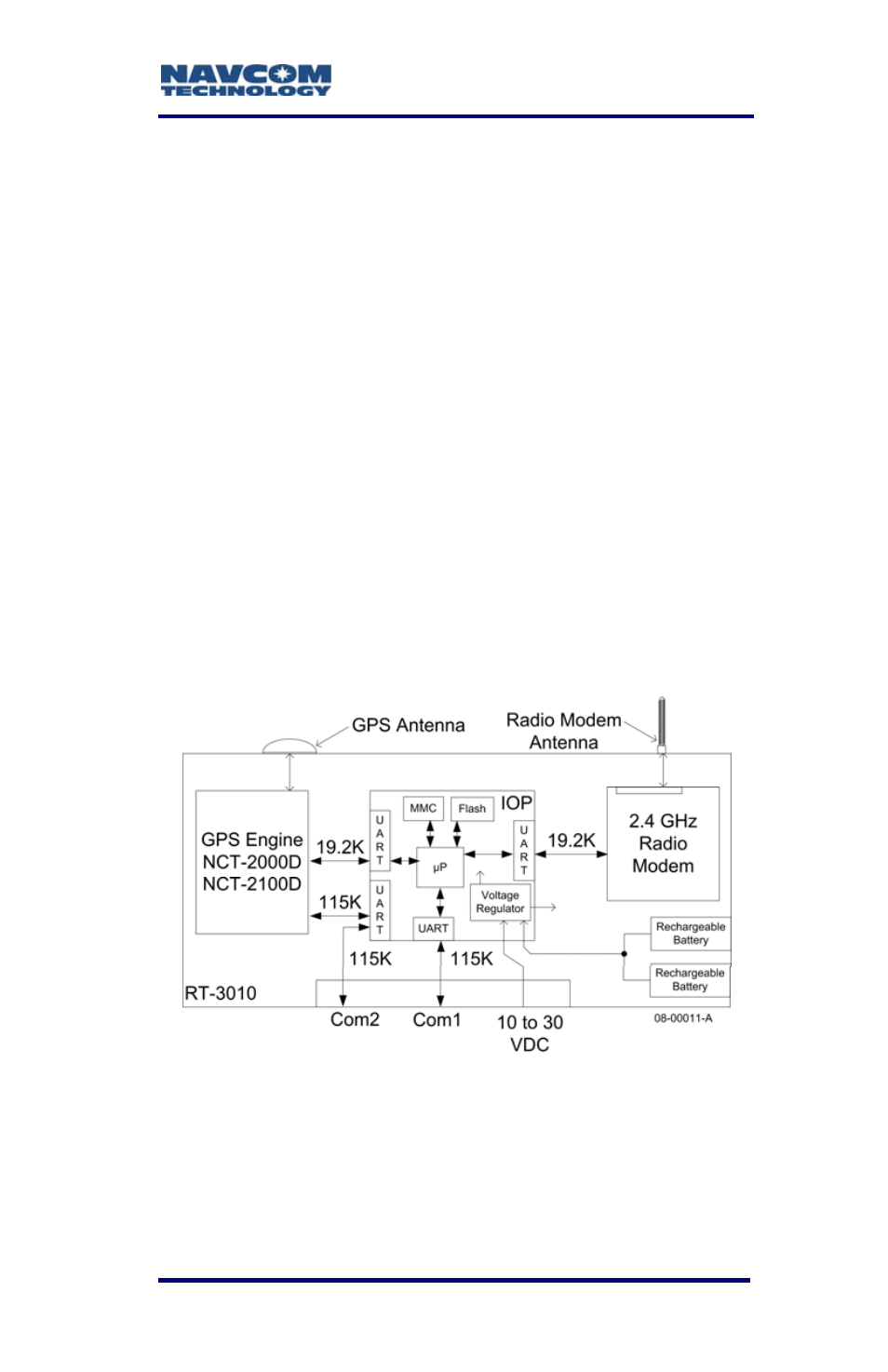
Block Diagrams
The RT-3010 has three user configurable physical
communications ports (two external and one internal)
and several logical communications ports. To aid in
distinguishing these ports, please refer to the block
diagram below.
Figure 8: RT-3010 Block Diagram
These user configurable physical ports
are Com1, Com2, and Radio/Diagnostic.
The Com ports are described in the next
section.
3-41
- SF-3050 Logging Data to Internal Memory SurvCE (4 pages)
- SF-3040 Logging Data to Internal Memory or SD Card (6 pages)
- SF-3050 Logging Data to USB Using SurvCE (4 pages)
- StarFire over IP (5 pages)
- SF-3050 Quick Start (4 pages)
- SF-3050 A Computationally Efficient Ambiguity Resolution (7 pages)
- StarFire (5 pages)
- StarFire to SW v3.0.12.0 (3 pages)
- SF-3050 Rev.I (196 pages)
- StarUtil-3000 Rev.G (177 pages)
- Sapphire Rev.L (450 pages)
- StarUtil-3000 Rev.A (119 pages)
- SF-3050 Rev.A (169 pages)
- SF-3050 Rev.B (201 pages)
- SF-3050 Rev.D (235 pages)
- Rinex Utility Rev.D (17 pages)
- SF-3040 Quick Start (4 pages)
- SF-3040 Rev.F (217 pages)
- SurveCE Integration Rev.A (150 pages)
- Install Utility Rev.C (26 pages)
- LAND-PAK Quick Start Rev.B (7 pages)
- LAND-PAK Rev.E (156 pages)
- StarUtil Rev.C (58 pages)
- LAND-PAK Rev.N (194 pages)
- StarUtil Rev.B (8 pages)
- StarUtil Rev.F (134 pages)
- SF-2040 Rev.E (63 pages)
- RT-3010 Rev.E (61 pages)
- StarFire Satellite Change Rev.G (24 pages)
- StarFire Satellite Change Rev.I (23 pages)
- TS Collecting Receiver (2 pages)
- TS Factory Default (2 pages)
- SF-2040 Rev.C (178 pages)
- LAND-PAK Rev.F (159 pages)
- SF-2040 Rev.F (93 pages)
- RT-3020 Rev.F (93 pages)
- SF-2110 Quick Start Rev.A (2 pages)
- StarPac Rev.A (15 pages)
- StarControl Rev.C (56 pages)
- SF-2050 Rev.F (99 pages)
- TruBlu Rev.A (2 pages)
- VueStar Rev.B (13 pages)
- SF-2110 Rev.B (99 pages)
- StarUtil-2110 Rev.A (85 pages)