Fire alarm control panel connection (input signal), Connecting fire alarm control panel to cm12, Dip switch configuration and setting – MovinCool CM12 User Manual
Page 15: Installation (cont.)
15
INSTALLATION (cont.)
Fire Alarm Control Panel Connection (Input Signal)
The CM12’s controller is equipped with a normal open input signal, which can be
connected directly from the fire alarm control panel. When receiving the signal
from the fire alarm control panel, the unit turns off and does not turn back on until
power source is reset or turns the wall thermostat off and on.
Connecting Fire Alarm Control Panel to CM12
1. Connect the fire alarm signal wires to CM12 signal wires label E+ and E-.
2. Use recommended fire alarm signal wire size from 16 AWG to 26 AWG for a
solid wire, or 16 AWG to 22 AWG for a stranded wire.
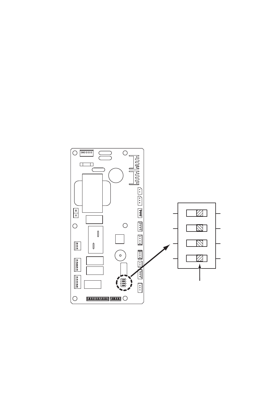
DIP Switch Configuration and Setting
The CM12’s controller is equipped with a 4-position DIP switch, which defaults in
the OFF position. The DIP switch can be set to configure the following functions:
a. When the switch position #1 is ON, the evaporator and condenser fan
motor turn on. This function is used for test purposes and verification.
b. When switch position #2 is ON, the compressor, evaporator and condenser
fan motor turn on. This function is used for test purposes and verification.
c. When switch position #3 is ON, the compressor delay timer function is
disabled.
d. When switch position #4 is ON, the buzzer sound function is disabled.
12
3
4
NO
“OFF” POSITION
250V 5A
OUTPUT
: 12.6V
-0.37A
GA09301-G ST
INPUT
: 230V 1
15V 0
CN01
CN15
CN16
CN14
CN02
CN03
CN04
CN17
CN25
CN23
CN22
CN21
4
3
52CH
RT
S
CTS
ODS
SW2
4-POSITION DIP SWITCH