Warning signal connection (output signal), Connecting warning signal from cm12, Installation (cont.) – MovinCool CM12 User Manual
Page 14
14
INSTALLATION (cont.)
Note: Use thermostat that is compatible with millivolt system. Do not connect
thermostat to AC power source.
5. Install the wall thermostat to the proper location inside the room where it can
be conveniently accessed. Do not install the wall thermostat where unusual
heating condition may occur (i.e. hot stove, hot pipe, fireplace, direct sunlight,
and etc.)
Most thermostats provide these basic functions:
Fan Mode: On / Auto (Select the desired fan mode)
System: Cool / Heater (Select Cool only)
Warning Signal Connection (Output Signal)
The CM12’s controller is equipped with a warning signal output relay type (Form-
C, normal open dry contact), which can be used to monitor the failure condition.
Relay contactor is closed when the following condition has occurred:
a. Condensation Overflow
b. Temperature Sensor fails
c. Cooling Function fails
The relay output contactor is rated 5 A at 30 VDC or 5 A at 250 VAC (resistive
load), and it is compatable with various warning devices such as alarm speakers,
light indicators, and etc.
Connecting Warning Signal From CM12
1. Connect the warning device to CM12 signal wires label L+ and L-.
2. Use recommended warning signal wire size from 16 AWG to 26 AWG for a
solid wire, or 16 AWG to 22 AWG for a stranded wire.
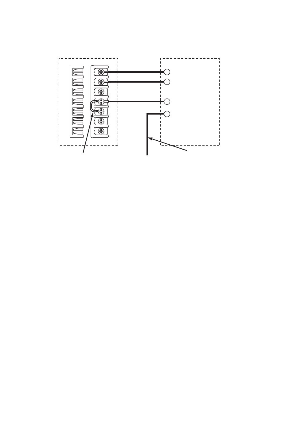
CM12 Unit
Thermostat
(Millivolt System)
Orange Wire
G
Y
RC
G1
Red Wire
GY
W
R
C
R
H
OB
Brown Wire
Yellow Wire
Remove Factory-Installed Jumper
Use only with thermostat that has
Fan Hi-Lo Speed control.