0 sensor installation, 1 sensor mounting orientation and tolerances, 2 verify sensor mounting surface height – MicroE Mercury II 6000 User Manual
Page 8: 3 install sensor, Sensor installation, Sensor mounting orientation and tolerances, Verify sensor mounting surface height, Install sensor
Sensor Installation
IM-Mercury_II_6000 Series Rev. 1
Page 7
©2014 MicroE Systems
Mercury
II
6000 Series Encoders
Installation Manual and Reference Guide
4.0 Sensor Installation
This section contains instructions for installing the sensor.
4.1
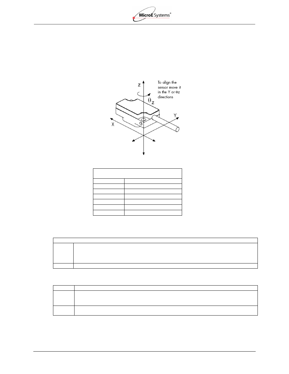
Sensor Mounting Orientation and Tolerances
Refer to the following specifications when installing and aligning the Mercury II 6000 encoder.
Orientation
Tolerances
Mercury II
Sensor Alignment Tolerances
Axis
Alignment Tolerance
X
Direction of Motion
Y
± 0.20mm
Z
± 0.15mm
X
± 1.0°
Y
± 1.0°
Z
± 2.0°
4.2
Verify Sensor Mounting Surface Height
Step
Action
1. Verify that the vertical distance between the reference surface of the sensor and the top of the
scale is as follows:
Tape scale/marker tape after blue protective film is removed: 3.09 mm +/-0.13
Linear or rotary glass scales: 2.93 mm +/-0.13
2. Check the height at a location on the scale where there are no index or limit markers.
4.3
Install Sensor
Step
Action
1. Install the sensor on the mounting surface referencing the appropriate datum surface as
shown in the MII6000 Interface Drawings. Use two M-2 screws to loosely attach the sensor.
Note: Do not tighten the two M2 screws at this time.
2. Use benching pins to locate the sensor if the system's mechanical tolerances are adequate.
Refer to the MII6000 Interface Drawings for recommended locations and heights of pins.
Sensor Axes