MicroE Mercury II 6000 User Manual
Page 19
Sensor Alignment and Calibration
IM-Mercury_II_6000 Series Rev. 1
Page 18
©2014 MicroE Systems
Mercury
II
6000 Series Encoders
Installation Manual and Reference Guide
Step
Action
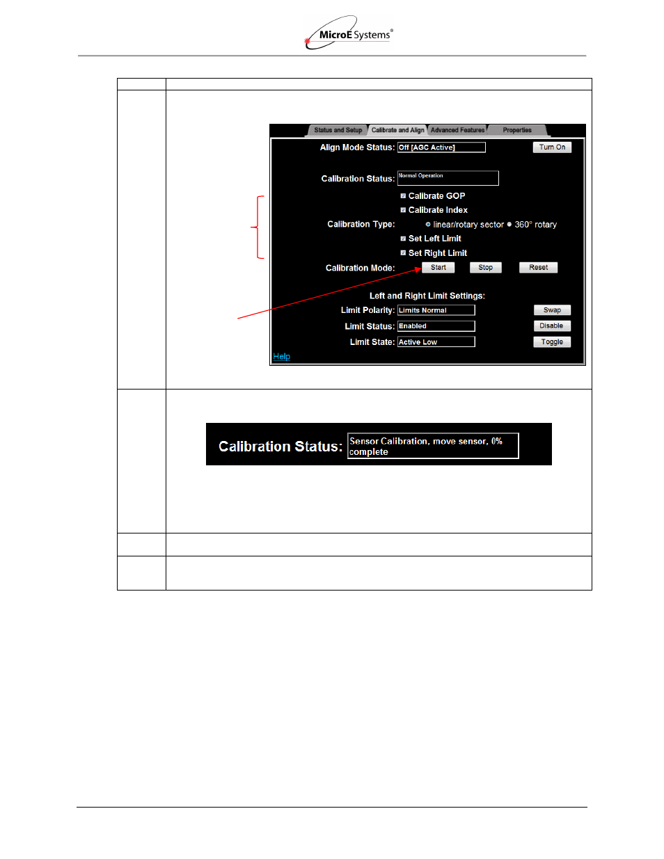
6. Perform setup by checking the Calibrate GOP, Calibrate Index, Set Left Limit, and Set Right
Limit boxes.
Note: Not all applications require all steps.
7. Ensure that the Calibration Type is correctly selected for your encoder (linear/rotary sector is
selected above). Press the Start button in Calibration Mode to begin calibration/setup.
Results: Sensor Calibration will begin. Follow the steps in the Calibration Status box to
complete setup of the MII6000 encoder. For example, in the status box above, the instructions
are to move the sensor until reaching 100% complete and then the next calibration step will
start.
8. If there is a failure, turn off the sensor and clean the scale. After cleaning, return to
5.2.3 Sensor Alignment and Calibration.
9. When calibration is complete, continue to the next section Alignment Verification with
Connector LEDs
to visually verify calibration using the LED indicators on the MII6000 sensor’s
connector.
Start Button
Check Boxes