MicroE Mercury II 6000 User Manual
Page 13
Sensor Alignment and Calibration
IM-Mercury_II_6000 Series Rev. 1
Page 12
©2014 MicroE Systems
Mercury
II
6000 Series Encoders
Installation Manual and Reference Guide
Note: Perform all procedures below at
≤1 meter/second relative motion between the sensor and
the scale.
Linear Scales or Rotary Scales used in applications less than <360°
Step
Action
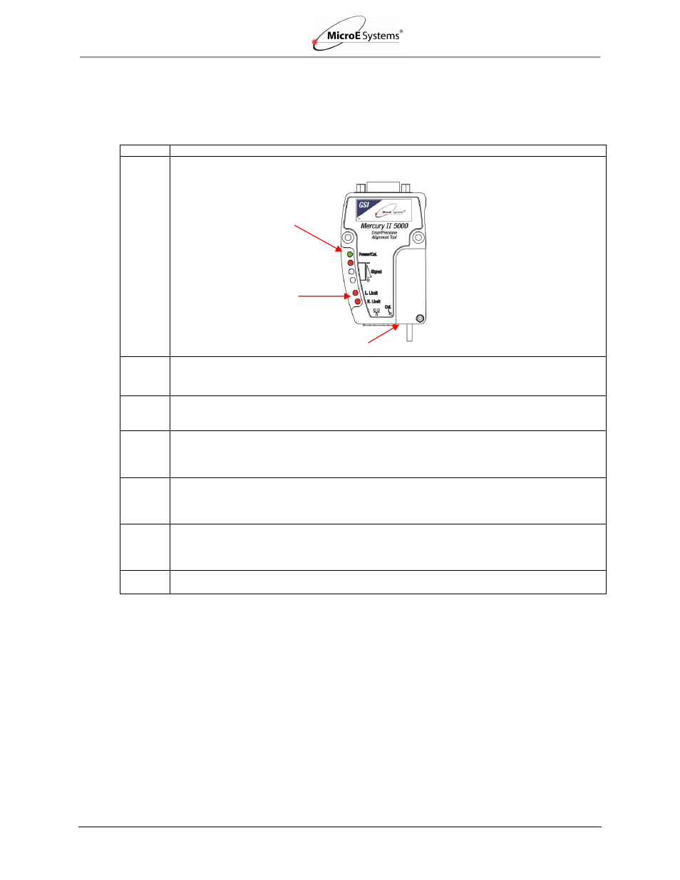
1. To start calibration, press and hold the Cal. button for about two seconds until the Power/Cal.
LED starts blinking slowly.
2. Move the sensor 50mm to perform Gain/Offset/Phase calibration. Move the sensor back and
forth if scale has <50mm of measuring length.
Result: After calibration both limit LEDs come on steady.
3. Move the sensor to an area of the scale away from the index and limit markers. Press the Cal.
button once quickly.
Result: The Power/Cal. LED will start blinking quickly.
4. Move the sensor over the index up to 20 passes (one pass is a single cycle back and forth).
Result: The Left Limit LED will start blinking quickly.
Note: If the sensor is positioned over the left limit marker, the Left Limit LED will come on
steady.
5. Move the sensor over the left limit marker and press the Cal. button once quickly.
Result: The Right Limit LED will start blinking.
Note: if the sensor is positioned over the right limit marker, the Right Limit LED will come on
steady.
6. Move the sensor over the right limit marker and press the Cal. button once quickly.
Result: All LEDs will flash together twice to indicate that setup is completed.
The encoder is now ready for connection to the controller for use in servo control.
7. When calibration is complete, go to
Section 6.0 Alignment Verification with Connector
to
visually verify calibration using the LED indicators on the MII6000 sensor’s connector.
Note: To skip any portion of this calibration and move to the next procedure, press and hold the
Cal. button for two seconds.
Power/Cal. LED
Cal. Pushbutton
Limit Switches LEDs